
Device for preventing wire from being wound and knotted and using method

A technology of wire rods and guide rods, applied in the field of wire rod pay-off devices, can solve the problems of easy overload shutdown of motors, affecting production efficiency, reducing production efficiency, etc.

Inactive Publication Date: 2021-08-10
GUANGDONG GUANGDONG SHAOGANG ENG TECH
View PDF9 Cites 0 Cited by
  • Summary
  • Abstract
  • Description
  • Claims
  • Application Information

AI Technical Summary

Problems solved by technology

It can be seen that the ways of wire rods are mainly divided into the rotation of the wire rod itself and the rotation of the wire rod driven by the shaft, that is, the existing wire rod wire rod device needs to release the wire rod while rotating the whole during the wire rod release process, but there are the following Disadvantages: The overall weight of the wire is relatively large, and the overall weight of some wires can be as high as several tons. During the rotation of the wire, the bearing of the circling mechanism is very easy to damage, especially if the circling mechanism is vertically set (that is, the wire is placed vertically). The bearing needs to bear the full weight of the wire, which is more likely to be damaged. The bearing of the spiral mechanism is damaged, and the bearing needs to be replaced, which affects production efficiency; for the way that the spiral mechanism drives the wire to rotate, the spiral mechanism needs to be synchronized with the straightening machine, which is inconvenient to set; for the wire itself The way of rotation, the rotation of the wire is completely dependent on the motor of the straightening machine to pull the wire to achieve, the motor of the straightening machine is easy to overload and stop, which reduces the production efficiency

Method used


Image

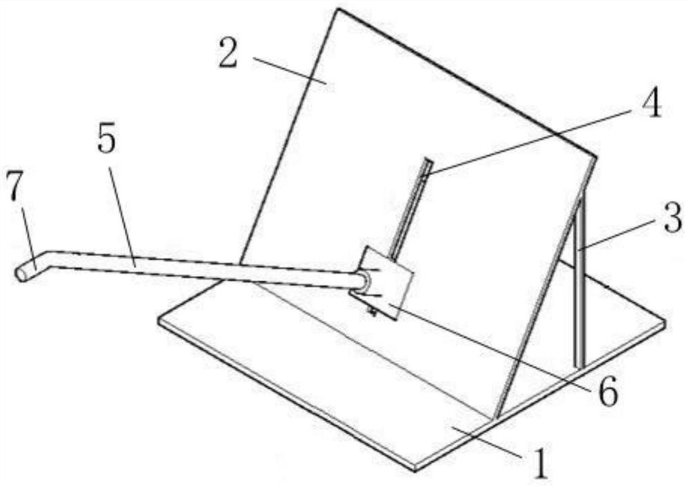
  • Device for preventing wire from being wound and knotted and using method
  • Device for preventing wire from being wound and knotted and using method
  • Device for preventing wire from being wound and knotted and using method

Examples


Embodiment Construction

[0025] The present invention will be described in detail below in conjunction with the accompanying drawings and embodiments.

[0026] It is worth noting that the orientation words such as "up" and "down" involved in this article are all determined relative to the perspective of the drawings, and are only for the convenience of description, and cannot be understood as limitations on the technical solution.

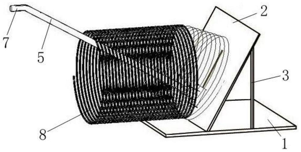
[0027] The wire rod 8 on the conventional pay-off device needs to be rotated because the wire rod 8 will be released naturally during the rotation process. When the wire device is set horizontally, that is, the wire 8 is placed horizontally, and the wire 8 will wind more and more tightly around the shaft passing through the wire 8 in the pay-off device, and the pay-off cannot be performed normally. When the pay-off device is vertically set, the wire 8 is vertical. placed, the overlapping wires 8 will be pulled out at the same time, and the phenomenon of winding and knottin...


PUM

PropertyMeasurementUnit
heightaaaaaaaaaa

Abstract

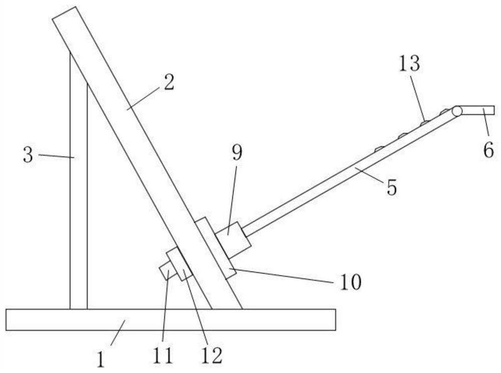
The invention relates to a device for preventing a wire from being wound and knotted and a using method thereof. The device comprises a horizontal base, a baffle and at least one traction guide rod, wherein the baffle is obliquely arranged on the horizontal base, a plurality of supporting rods are arranged between the baffle and the horizontal base, an adjusting groove is vertically formed in the middle of the baffle, an adjusting pipe seat matched with the adjusting groove is arranged at the bottom end of the traction guide rod, the adjusting pipe seat is fixedly arranged on the baffle through the adjusting groove, the traction guide rod is fixed on the baffle through the adjusting pipe seat, the included angle between the traction guide rod and the horizontal base is an acute angle, and a buffer rod extending outwards is arranged at the top end of the traction guide rod. According to the device, in the paying-off process, the wire is pulled out by a straightening machine, the wire does not need to rotate, the load of the straightening machine is reduced, and meanwhile, normal paying-off of the wire is not influenced.

Description

technical field [0001] The present invention relates to a wire pay-off device, more specifically, it relates to a device for preventing wire from being entangled and knotted and a method of use thereof. Background technique [0002] When the wire is sold, it is generally sold in the form of a whole bundle or wound on a cylinder. When using these wires, it is necessary to straighten the wires during the unwinding process to prevent the twisted and knotted wires from entering the straightening machine. Inside. The conventional way of paying off the wire will vary according to the form of the wire. If the wire is in the form of a bundle, the whole bundle of wire is generally placed on a rotatable roller, and the roller is installed on a vertically or horizontally arranged circling mechanism, and the roller rotates on the circling mechanism or the circling mechanism drives the roller Rotation; if the wire is wound on the cylinder, the cylinder is placed on a vertically or hori...

Claims


Application Information

Patent Timeline
Patent Type & Authority Applications(China)
IPC IPC(8): B21C47/22B21F1/02B21F11/00B21F23/00
CPCB21C47/22B21F1/026B21F11/00B21F23/00
Inventor 韩赞文唐柏杨宁华立侯舒哲黄钟光文辉崔振飞赵星震陈志光谭志尉刘美剑范长江李红利
Owner GUANGDONG GUANGDONG SHAOGANG ENG TECH
Learn More