Mobile charging equipment for new energy automobile
A technology for new energy vehicles and charging equipment, applied in electric vehicle charging technology, charging stations, electric vehicles, etc., can solve problems such as too many charging piles and waste of resources, to avoid offset, prevent shortened service life, and avoid resources wasteful effect
- Summary
- Abstract
- Description
- Claims
- Application Information
AI Technical Summary
Problems solved by technology
Method used
Image
Examples
Embodiment 1
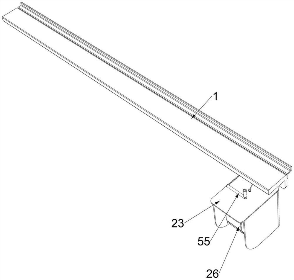
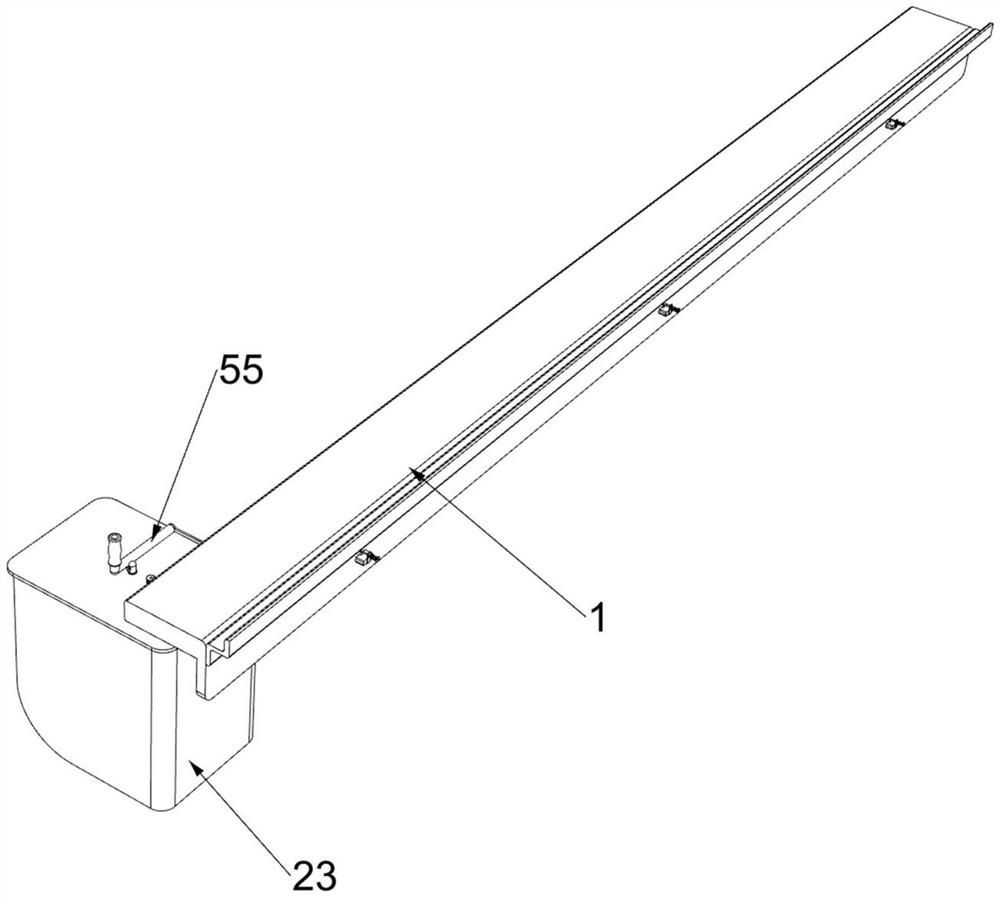
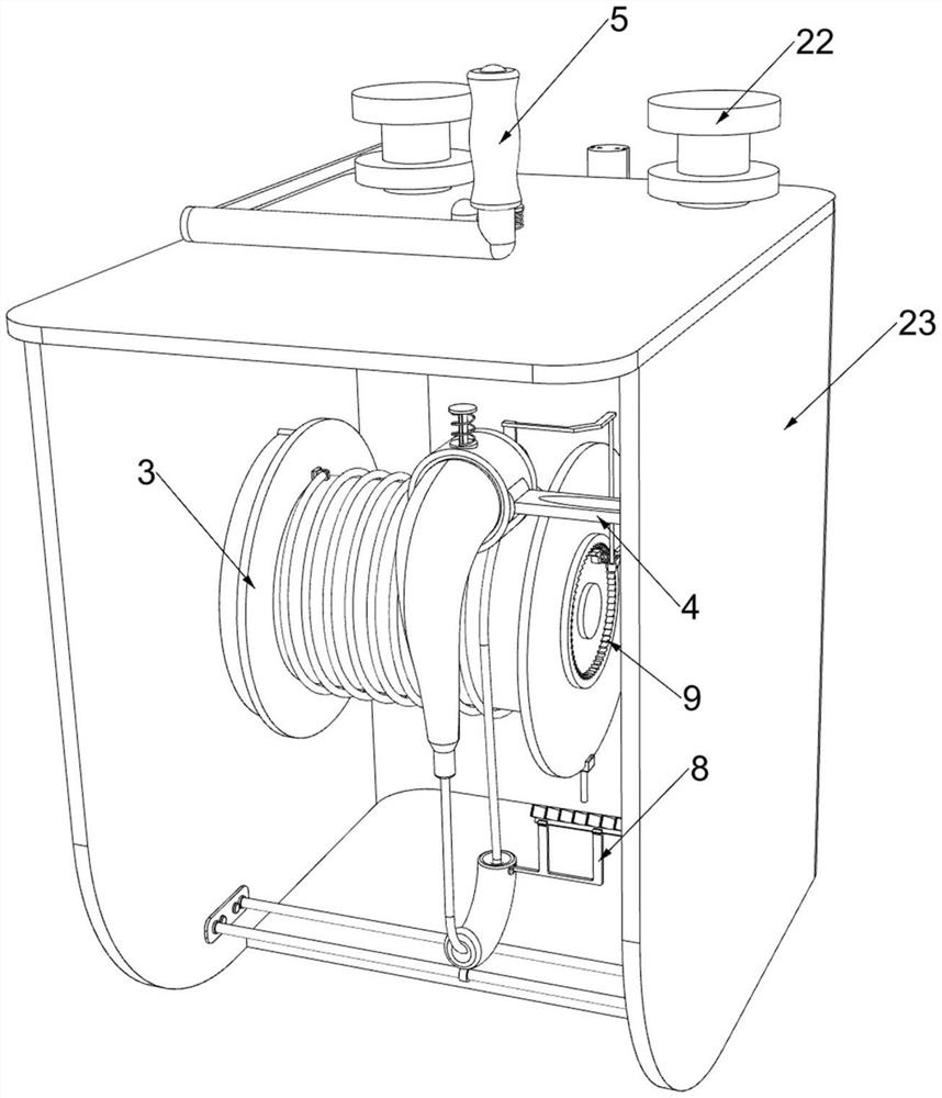
[0054] A mobile charging device for new energy vehicles, such as figure 1 , figure 2 , image 3 , Figure 4 , Figure 5 , Image 6 , Figure 7 , Figure 8 , Figure 9 , Figure 10 , Figure 17 , Figure 18 , Figure 20 with Figure 21 As shown, it includes a supporting slide rail 1, a power socket 21, a supporting sliding column 22, a supporting frame 23, a sliding supporting frame 24, a power plug 25, a protective plate 26, a first supporting frame 27, a second supporting frame 28, a winding winding Part 3 and placement assembly 4, power outlets 21 are installed in a uniform arrangement on the support slide rail 1, two support slide columns 22 are slidably connected on the support slide rail 1, and two support slide columns 22 are connected with support The frame 23, the sliding support frame 24 is slidably connected to the support frame 23, the power plug 25 is fixedly connected to the sliding support frame 24, the protective plate 26 is fixedly installed on the...
Embodiment 2
[0060] On the basis of Example 1, such as figure 1 , figure 2 , Figure 10 , Figure 11 , Figure 12 , Figure 13 , Figure 14 with Figure 15 As shown, it also includes an anti-deviation assembly 5, the support frame 23 is provided with an anti-deviation assembly 5, the anti-deviation assembly 5 is used to prevent the position of the power plug 25 from shifting, and the anti-deviation assembly 5 includes a third support Frame 51, sliding frame 52, second spring 53, limit block 54, the first push frame 55, perforated plate 56, card column frame 57, the 3rd spring 58, hollow column 59, slotted push frame 510 and limit frame 511, one side of the support frame 23 is fixedly connected with a third support frame 51, the third support frame 51 is slidably connected with a sliding frame 52, the sliding frame 52 is fixedly connected with a second spring 53, and the second spring 53 is far away from the sliding frame 52. One end of the spring 53 is connected with the third supp...
Embodiment 3
[0063] On the basis of Example 2, such as Figure 15 with Figure 16 As shown, it also includes a clamping assembly 6, the sliding frame 52 is provided with a clamping assembly 6, the clamping assembly 6 is used to clamp the limit block 54, the clamping assembly 6 includes a fourth support frame 61, a rotation guide Frame 62, the first torsion spring 63, toggle frame 64, support rod 65 and the 4th spring 66, the sliding frame 52 is fixedly connected with the 4th support frame 61, and the 4th support frame 61 is connected with the rotation guide frame 62 , the first torsion spring 63 is connected between the rotation guide frame 62 and the fourth support frame 61, and the toggle frame 64 is fixedly connected to the limit block 54, and the rotation guide frame 62 is used to block the toggle frame 64, close to the limit The support slide rail 1 of the block 54 is connected with support rods 65 in a uniform arrangement, and the support rods 65 are slidably connected with the limi...
PUM
 Abstract
Description
Claims
Application Information
 - R&D
- Intellectual Property
- Life Sciences
- Materials
- Tech Scout
- Unparalleled Data Quality
- Higher Quality Content
- 60% Fewer Hallucinations
Browse by: Latest US Patents, China's latest patents, Technical Efficacy Thesaurus, Application Domain, Technology Topic, Popular Technical Reports.
© 2025 PatSnap. All rights reserved.Legal|Privacy policy|Modern Slavery Act Transparency Statement|Sitemap|About US| Contact US: help@patsnap.com


