Ultrasonic bolt stress detection device

A technology for detecting device and bolt stress, applied in the direction of measuring device, measuring force, instrument, etc., can solve problems such as too tight or too loose bolts, collapse of the overall structure, inconvenient use, etc., to prevent the probe from falling off, easy to move, and convenient The effect of storing the probe

Pending Publication Date: 2021-08-10
国能长源湖北新能源有限公司
View PDF0 Cites 0 Cited by
  • Summary
  • Abstract
  • Description
  • Claims
  • Application Information

AI Technical Summary

Problems solved by technology

The prestress applied on it has a great influence on the performance and life of the joints. The tightening force of the bolts on the joints is different, which will cause the bolts to be too tight or too loose, which may cause the bolts to break
Therefore, in addition to the stress of the fastening bolts should meet the design requirements, the stress of all bolts on the same connection joint should be uniform. A large number of bolts will be used for fastening in the connection structure of some large devices, but if multiple groups of bolts The fastening force is different, and under different stress pulls, the bolts may break, resulting in the collapse of the overall structure
[0003] Therefore, a stress detection device is needed to detect the stress of the bolt, but the existing bolt stress detection device is inconvenient to use during detection

Method used


Image

  • Ultrasonic bolt stress detection device
  • Ultrasonic bolt stress detection device
  • Ultrasonic bolt stress detection device

Examples


Embodiment 1

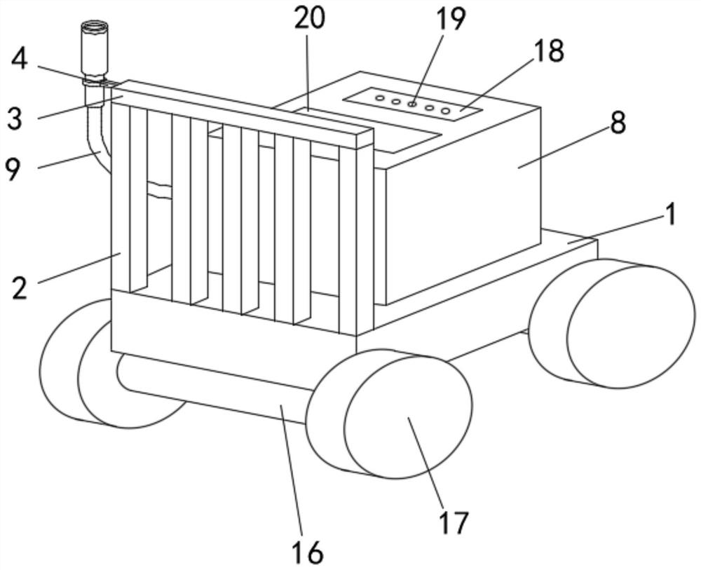
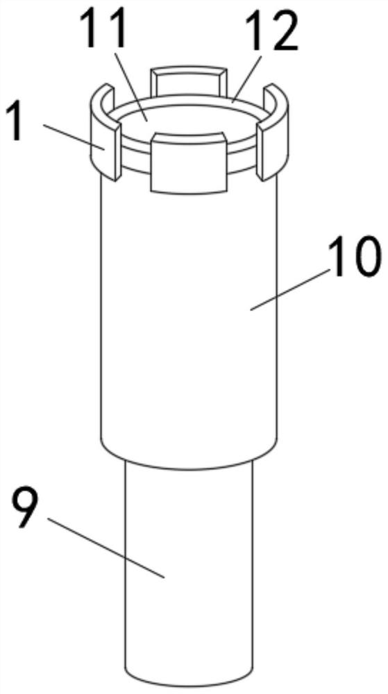
[0027] One end above the detection device base 1 is provided with an ultrasonic detection device body 8, one end of the ultrasonic detection device body 8 is electrically connected to a probe wire 9, and one end of the probe wire 9 is provided with an electromagnetic coil compartment 10, and the electromagnetic coil compartment 10 is provided with a detection probe 11 , and one end of the electromagnetic coil chamber 10 is provided with an electromagnetic adsorption metal ring 12 .

Embodiment 2

[0029] One end of the electromagnetic coil warehouse 10 is provided with a telescopic rod 13, and one end of the telescopic rod 13 is provided with a bolt buckle plate 14, and the outer side of the telescopic rod 13 is provided with a return spring 15, and the two ends of the telescopic rod 13 and the return spring 15 are The electromagnetic coil chamber 10 and the bolt buckle plate 14 are respectively connected, and the number of the telescopic rod 13 , the bolt buckle plate 14 and the return spring 15 are all provided in four groups.

Embodiment 3

[0031] A wheel shaft 16 is arranged under the base 1 of the detection device, and a moving roller 17 is arranged at one end of the wheel shaft 16, and there are multiple groups of the wheel shaft 16 and the moving roller 17.


PUM


Abstract

The invention discloses an ultrasonic bolt stress detection device which comprises a detection device base, one end of the detection device base is fixedly connected with a device handrail supporting rod, one end of the device handrail supporting rod is fixedly connected with a device transverse handrail, one end of the device transverse handrail is fixedly connected with a probe buckle fixing rod, one end of the probe buckle fixing rod is provided with a probe buckle clamping groove, one end of the probe buckle clamping groove is in buckle connection with a probe buckle convex block, and one end of the probe buckle convex block is fixedly connected with a probe buckle. According to the size and specification of a probe, the probe buckle with the appropriate specification is selected, the probe buckle convex block at one end of the probe buckle is buckled into the probe buckle clamping groove, and the probe buckle is buckled on the probe buckle fixing rod; and when the probe is not used, a probe wire penetrates through a circular opening in one end of the probe buckle, and an electromagnetic coil bin is placed on the probe buckle, so that the probe can be conveniently stored, and the use is convenient.

Description

technical field [0001] The invention relates to the technical field of stress detection, in particular to an ultrasonic bolt stress detection device. Background technique [0002] As a fixed connection structure with simple structure and convenient disassembly and assembly, bolts are widely used in large-scale infrastructure and complete sets of equipment such as wind power, bridges, and cranes. The prestress applied on it has a great influence on the performance and life of the joints. The tightening force of the bolts on the joints is different, which will cause the bolts to be too tight or too loose, which may cause the bolts to break. Therefore, in addition to the stress of the fastening bolts should meet the design requirements, the stress of all bolts on the same connection joint should be uniform. A large number of bolts will be used for fastening in the connection structure of some large devices, but if multiple groups of bolts The fastening force is different, and ...

Claims


Application Information

Patent Timeline
Patent Type & Authority Applications(China)
IPC IPC(8): G01L1/25
CPCG01L1/255
Inventor 胡保红曾江卓杨旭叶子青卿松乔冠瑜宋波
Owner 国能长源湖北新能源有限公司
Why Eureka
Try Eureka