Spring grinding machine

A spring grinding machine and grinding technology, which is applied in the field of spring processing, can solve the problems of low efficiency of spring end replacement, and achieve the effect of not easy displacement, stable installation, and high efficiency of end replacement

Active Publication Date: 2021-08-17
ZHEJIANG JINCHANG SPRING CO LTD
View PDF6 Cites 4 Cited by
  • Summary
  • Abstract
  • Description
  • Claims
  • Application Information

AI Technical Summary

Problems solved by technology

[0005] After the grinder grinds one end of the spring, it is necessary to manually remove the spring, turn it over and put it back into the fixing seat, so as to grind the other end of the spring. When there are many springs, it is necessary to manually replace all the springs in sequence. end, making the spring exchange end less efficient

Method used


Image

  • Spring grinding machine
  • Spring grinding machine
  • Spring grinding machine

Examples


Embodiment 1

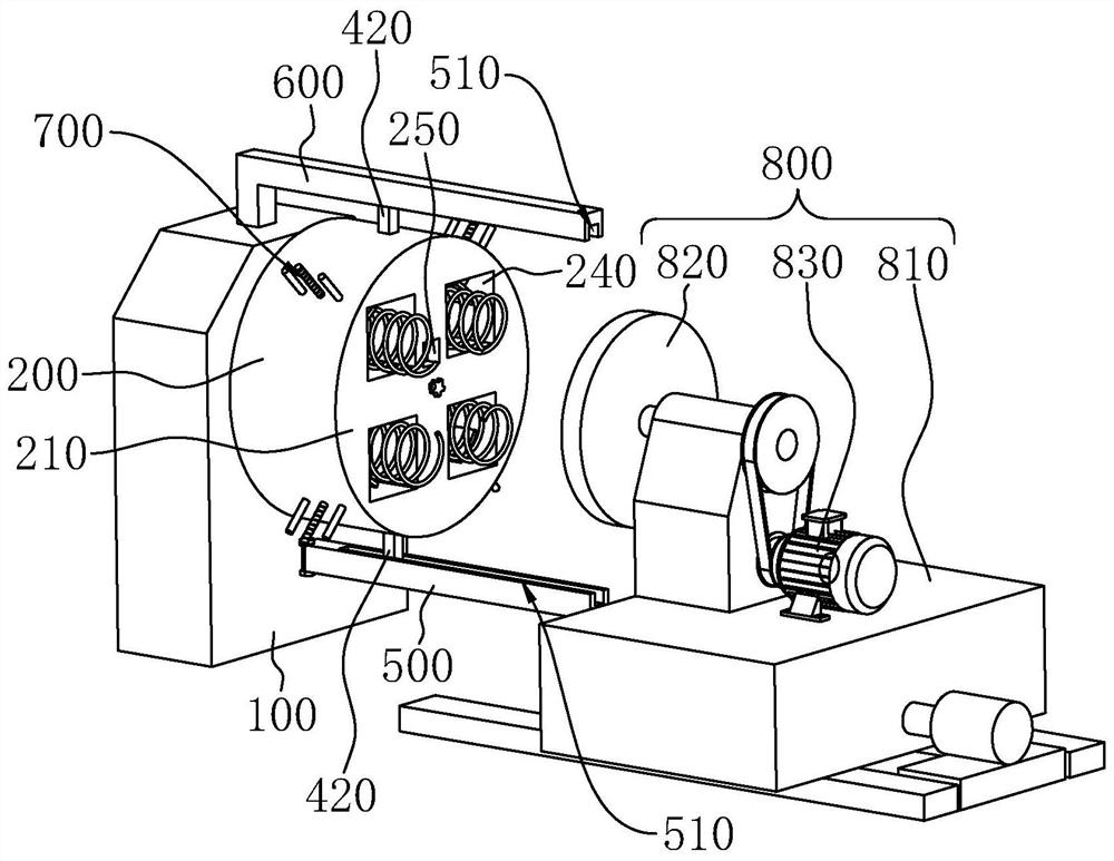
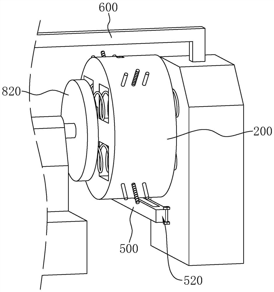
[0041] Embodiment 1: The embodiment of this application discloses a spring grinding machine, refer to figure 1 and figure 2 , including a grinding mechanism 800 and a clamping mechanism, the grinding mechanism 800 is located on one side of the clamping mechanism, and the grinding mechanism 800 is slidably installed in a direction approaching / far away from the clamping mechanism through a cylinder and a slide rail.

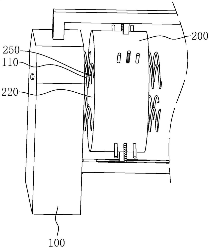
[0042] The clamping mechanism includes a frame 100 and a mounting frame 200. The mounting frame 200 is a cylinder, and the eccentric parts of both ends of the mounting frame 200 are provided with a connecting groove 250 with a square cross section. The frame 100 is fixedly connected with a connecting block 110, and the connecting block The cross-section of 110 fits with the connection groove 250 , and the connection block 110 is embedded in the connection groove 250 , so that the installation frame 200 is detachably connected to the frame 100 in the circumferentia...

Embodiment 2

[0064] Embodiment 2: refer to Figure 7 , the difference from Embodiment 1 is that the installation frame 200 is rotatably connected with the installation plate 900, the rotation axis of the installation plate 900 is set horizontally, the second motor 120 is installed on the frame 100, and the second motor 120 is driven and installed by a belt. The plate 900 is connected and drives the mounting plate 900 to rotate, and the rotating direction of the mounting frame 200 is opposite to that of the grinding disc 820 . The second motor 120 drives the mounting frame 200 to rotate, which can improve the grinding efficiency.

[0065] A side of the mounting plate 900 away from the second motor 120 is fixedly connected with a plurality of inserting blocks 910 , and two ends of the mounting frame 200 are provided with a plurality of slots 920 , the cross sections of the inserting blocks 910 match the cross sections of the slots 920 . The middle part of the insert block 910 is fixedly con...


PUM


Abstract

The invention relates to a spring grinding machine and relates to the technical field of spring machining. The spring grinding machine comprises a grinding mechanism and a clamping mechanism, wherein the grinding mechanism is located on one side of the clamping mechanism, the clamping mechanism comprises a rack and a mounting rack used for mounting a plurality of springs to be machined, the mounting rack is mounted on the rack and is provided with a first working face and a second working face, when the first working face faces the grinding mechanism, the clamping mechanism is in a first working state, and when the second working face faces the grinding mechanism, the clamping mechanism is in a second working state, and the clamping mechanism is connected with an end changing mechanism used for switching the working state of the clamping mechanism. The spring grinding machine has the effects that when the ends of the multiple springs need to be changed, sequential operations are not needed, and the spring end changing efficiency is high.

Description

technical field [0001] The present application relates to the technical field of spring processing, in particular to a spring grinding machine. Background technique [0002] In the process of spring processing, after the spring is coiled and formed, in order to ensure the verticality of the coil spring, and to keep the end faces of the two supporting rings in contact with other parts, and to reduce the characteristics of deflection, both ends of the coil spring are generally ground. Cutting, this process is usually called grinding spring. Usually, a spring grinding machine is used to automatically grind the end face of the spring. [0003] For example, the authorized announcement number is CN103639862B, and the application date is December 4, 2013. The Chinese patent discloses a spring grinding machine, including a first frame body, a partition, a connecting shaft, a first motor pump group, a valve group, a first Hydraulic cylinder, grinder device, connecting arm, support ...

Claims


Application Information

Patent Timeline
Patent Type & Authority Applications(China)
IPC IPC(8): B24B7/16B24B41/06B24B41/02B24B41/00
CPCB24B7/167B24B41/067B24B41/02B24B41/00
Inventor 费庆民金炳余薄家曜
Owner ZHEJIANG JINCHANG SPRING CO LTD
Why Eureka
Try Eureka