
Shifting device for dial switches

A toggle device and DIP switch technology, applied in the direction of contact operating parts, etc., can solve the problems of inability to flexibly transfer the site, occupying installation space, and a large number of cylinders, and achieve a simple structure, low cost, and high toggle efficiency. Effect

Pending Publication Date: 2019-11-19
AUTOBIO LABTEC INSTR CO LTD
View PDF1 Cites 0 Cited by
  • Summary
  • Abstract
  • Description
  • Claims
  • Application Information

AI Technical Summary

Problems solved by technology

Although the toggling mechanism can realize the toggling action of four sets of DIP switches (generally, each set of DIP switches has two keys); but since each paddle can only toggle one key, each cylinder can only drive One paddle, so the number of cylinders is extremely large, and the cost is high; and the eight cylinders all need air sources, occupying installation space, and cannot be flexibly moved

Method used


Image

  • Shifting device for dial switches
  • Shifting device for dial switches
  • Shifting device for dial switches

Examples


Embodiment Construction

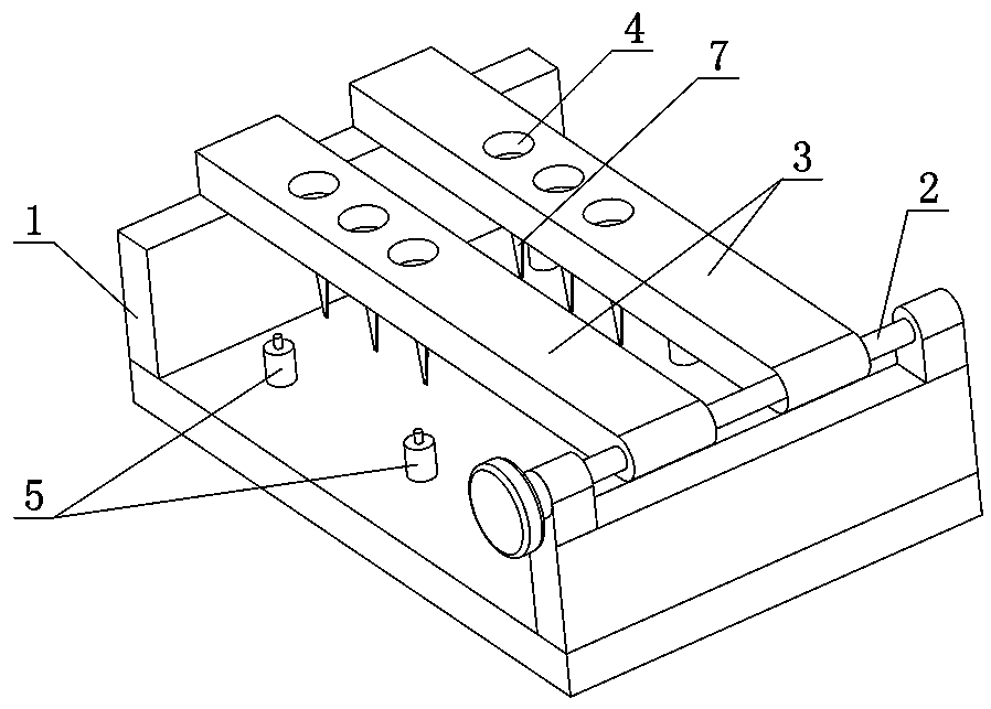
[0016] Such as figure 1 As shown, the dial switch toggle device according to the present invention includes a base 1 in a U-shaped structure and a toggle mechanism arranged on the base 1. The toggle mechanism includes a pair of The mounting plate 3 on the top of one side wall of the base 1, the other end of the two mounting plates 3 is placed on the top of the other side wall of the base 1; each mounting plate 3 is slidably matched with the hinge shaft 2 for easy operation; each Three mounting holes 4 are provided at intervals on the mounting plate 3 (the mounting holes 4 are threaded holes, of course, the actual demand mounting holes 4 can also be four, five or more), and each mounting hole 4 is provided with a Move the handle of the dial switch, and turn any one or two digits of the two-digit dial switch from the digital side to the ON side; the upper surface of the bottom plate of the base 1 is provided with four pillars 5 for supporting the circuit board at intervals, The...


PUM


Abstract

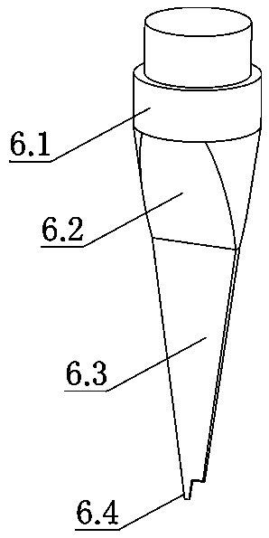
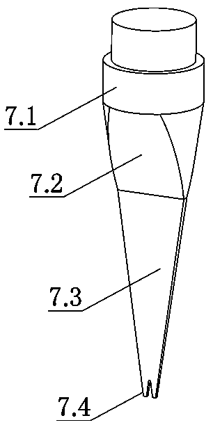
The invention discloses a shifting device for dial switches. The shifting device comprises a base and a shifting mechanism arranged on the base; the base is of a U-shaped structure; the shifting mechanism comprises a mounting plate hinged to the top of one side wall of the base through a hinge shaft; one end of the mounting plate is lapped on the top of the other side wall of the base; the mounting plate is in sliding fit with the hinge shaft; and shifting arms for shifting the dial switches are arranged in the mounting holes of the mounting holes respectively. The shifting device has the advantages of simple structure, light weight, low cost and simple and fast to operate. The shifting device can be flexibly transferred to any position. According to the shifting device adopted, the corresponding one-pin shifting arms or two-pin shifting arms are correspondingly arranged in the mounting plate according to the position of each set of dial switch on a circuit board; and therefore, the shifting requirements of a plurality of dial switches on different circuit boards can be satisfied, shifting efficiency is high, and missed operation or wrong shifting can be completed avoided.

Description

technical field [0001] The invention relates to an auxiliary appliance for electronic components, in particular to a toggle device for a dial switch. Background technique [0002] As a micro switch that requires manual operation, the DIP switch is widely used in many equipment products such as communication, security, and automated medical testing. The DIP switch is usually welded on the integrated circuit board of the device. Each integrated circuit board may involve the use of multiple sets of DIP switches. Each key of the DIP switch is located on the digital side in the factory state, and each key corresponds to There are two pins on the upper and lower sides of the back of the switch. Toggle the pin on the ON side to conduct, otherwise it will be disconnected. In order to realize various automatic actions, the states of each DIP switch on the integrated circuit board are different. [0003] The traditional dial switch test method is manual dial, that is, manually use f...

Claims


Application Information

Patent Timeline
Patent Type & Authority Applications(China)
IPC IPC(8): H01H3/02
CPCH01H3/02
Inventor 韩伟娜李瑞丽刘桐瑞王士文卢鑫高艳彩刘聪
Owner AUTOBIO LABTEC INSTR CO LTD
Learn More