Supercharge Your Innovation With Domain-Expert AI Agents!

Wear indication device for a flow control valve

A technology of flow control and equipment, which is applied in the direction of sliding valves, mechanical equipment, devices for absorbing fluid energy of valves, etc., and can solve problems such as damage to the internal parts of the valve, strong, bursting of the steam chamber, etc.

Pending Publication Date: 2021-08-17
FISHER CONTROLS INT LLC
View PDF0 Cites 0 Cited by
  • Summary
  • Abstract
  • Description
  • Claims
  • Application Information

AI Technical Summary

Problems solved by technology

When the vapor chamber in the fluid is subjected to higher pressure, the vapor chamber bursts and generates a strong shock wave which may damage the internal parts of the valve or produce an audible noise

Method used


Image

  • Wear indication device for a flow control valve
  • Wear indication device for a flow control valve
  • Wear indication device for a flow control valve

Examples


Embodiment Construction

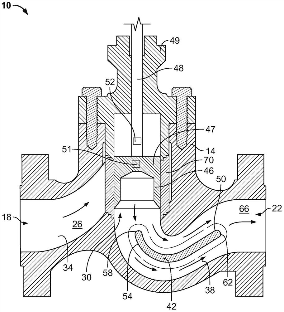
[0032] The present disclosure provides detection apparatus and methods for detecting wear due to cavitation or corrosion on flow control valve components. exist figure 1 In the present disclosure, a first exemplary flow control device 10 indicative of wear due to cavitation was constructed in accordance with the teachings of the present disclosure. The flow control device 10 is a sliding stem type control valve (e.g., HP series valve), which includes a ball valve body 14 defining an inlet 18, an outlet 22, and a flow path 26 connecting the inlet 18 and the outlet 22. Valve body 14 includes a valve port 30 defined between inlet 18 and outlet 22 , an inlet passage 34 , an outlet passage 38 , and flow vanes 42 . An inlet passage 34 connects the inlet 18 with the valve port 30 and an outlet passage 38 connects the valve port 30 with the outlet 22 .

[0033] A control member 46 is disposed in the flow path 26 and is movable relative to the valve port 30 in the valve body 14 bet...


PUM


Abstract

A flow control device includes a valve body having an inlet, an outlet, and a flow path connecting the inlet and the outlet. A flow vane is coupled to the valve body and disposed in the flow path to divide a flow of fluid through the valve body. The flow vane has a first surface, a second surface, and a corrugation formed on at least one of the first and second surfaces. A control element is disposed in the flow path and movable in the valve body between an open position and a closed position.

Description

technical field [0001] The present disclosure relates generally to flow control valves, and more particularly, to flow vanes of flow control valves. Background technique [0002] In some control valves, fluctuating pressure waves caused by fluid flowing through the control valve create unwanted noise. For example, hydrodynamic noise may be caused by cavitation, the formation and collapse of vapor cavities in a flow stream subjected to rapid pressure changes. When the vapor cavity in the fluid is subjected to higher pressure, the vapor cavity bursts and generates a strong shock wave which can damage internal parts of the valve or produce an audible noise. Damage from cavitation occurs gradually, and if detected early enough, valve components can be replaced to avoid leaks and / or valve failure. Contents of the invention [0003] According to a first exemplary aspect, a flow control device may include a valve body having an inlet, an outlet, and a flow path connecting the i...

Claims


Application Information

Patent Timeline
Patent Type & Authority Applications(China)
IPC IPC(8): F16K27/04F16K3/24F16K47/02F16K37/00G01B17/02G01B17/00
CPCF16K27/041F16K3/24F16K47/02F16K37/00G01B17/02G01B17/00F16K37/0041F16K37/0008F16K3/32G01N29/09G01B17/04
Inventor P·T·奥尔曼A·J·金斯尔R·S·科里森
Owner FISHER CONTROLS INT LLC
Features
  • R&D
  • Intellectual Property
  • Life Sciences
  • Materials
  • Tech Scout
  • Unparalleled Data Quality
  • Higher Quality Content
  • 60% Fewer Hallucinations
Learn More