
Five-level clamping cross type sub-module topological structure of modular multi-level converter
A modular multi-level, topological structure technology, applied in power transmission AC network, AC power input conversion to DC power output, electrical components, etc. It solves the problems of heavy load on the device, and achieves the effect of safe and reliable operation of the topology, reducing hardware costs, and reducing the burden.
- Summary
- Abstract
- Description
- Claims
- Application Information
AI Technical Summary
Problems solved by technology
Method used
Image

Examples
Embodiment Construction
[0090] The present invention will be further described below with reference to the accompanying drawings and specific embodiments.
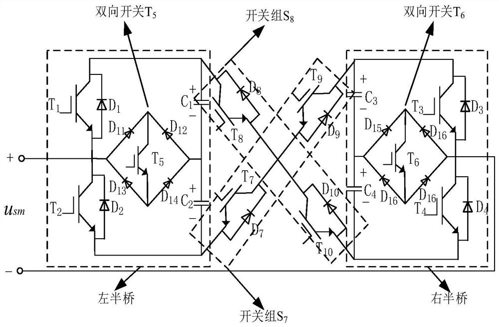
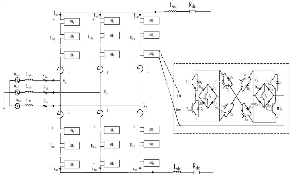
[0091] like figure 1 As shown, a five-level clamped cross-type sub-module topology structure of a modular multi-level converter with DC fault clearance capability includes an MMC sub-module topology, and the MMC sub-module topology includes a sub-module output end, so The output terminals are the voltage positive output terminal and the voltage negative output terminal, and the sub-module structure also includes two left and right half bridges with the same structure, and the two half bridges pass through the crossed power switch group S. 7 and S 8 connected, the switch group S 7 is composed of an insulated gate bipolar transistor T 7 and its anti-parallel diode D 7 Switches and Insulated Gate Bipolar Transistors T 9 and its anti-parallel diode D 9 The switches are set up in series; the switch group S 8 is composed of an insulated gate bip...
PUM
 Abstract
Description
Claims
Application Information