Multi-camera control method, device, system and electronic device

A control method and camera technology, which is applied to the parts of the TV system, TV, electrical components, etc., can solve the problems of waste of resources, low control accuracy of multi-eye cameras, etc., and achieve the effect of concise and easy-to-understand goals and advantages

Active Publication Date: 2022-06-03
ZHEJIANG DAHUA TECH CO LTD
View PDF8 Cites 0 Cited by
  • Summary
  • Abstract
  • Description
  • Claims
  • Application Information

AI Technical Summary

Problems solved by technology

[0005] Embodiments of the present application provide a multi-camera control method, device, system, and electronic device to at least solve the problem of low control accuracy of multi-cameras and waste of resources in the related art

Method used


Image

  • Multi-camera control method, device, system and electronic device
  • Multi-camera control method, device, system and electronic device
  • Multi-camera control method, device, system and electronic device

Examples


Embodiment Construction

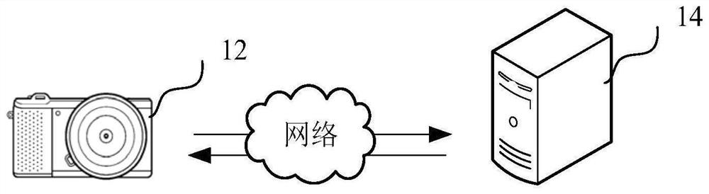
[0053] The control method of the multi-camera provided by the present application can be applied to the application environment as shown in FIG. 1 . That

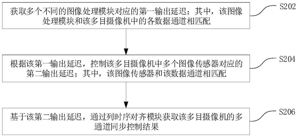
[0063] Therefore, through the above steps S202 to S206, by controlling a plurality of image sensors in the multi-eye camera to pair

[0067] Step S304, when detecting that at least one of the switches is enabled as a second preset switch, control all

[0068] Similarly, the above-mentioned second preset switch enable can be selected and set in advance by the staff; for example, the staff

[0069] Through the above-mentioned steps S302 to S304, it is judged whether the switch enabling corresponding to each algorithm unit is the second preset

[0070] In some of the embodiments, FIG. 4 is another method for controlling a multi-camera camera according to an embodiment of the present application

[0075] In some of these embodiments, after performing the above step S206, the above-mentioned control method for a multi-camera camera ...


PUM


Abstract

The present application relates to a multi-camera control method, device, system and electronic device, wherein the control method includes: acquiring the first output delays corresponding to multiple different image processing modules; wherein the image processing module and the multiple Each data channel of the camera is matched; according to the first output delay, control the second output delay corresponding to a plurality of image sensors in the multi-camera; wherein, the image sensor is matched with the data channel; based on the second output Delay, obtain the multi-channel synchronous control result of the multi-camera through the column timing alignment module. Through the present application, the problems of low control accuracy of multi-cameras and waste of resources are solved, and a multi-camera control method based on output timing control is realized.

Description

Control method, device, system and electronic device for multi-eye camera technical field [0001] The application relates to the technical field of video surveillance, in particular to a control method, device, system and electronic device. Background technique [0002] The multi-eye camera is a more commonly used imaging device, and the body of the multi-eye camera is equipped with a plurality of lenses. The lenses are distributed along the circumference of the body. In the field of multi-camera monitoring, the central processing unit (Central Processing Unit, referred to as CPU) or coprocessor to control the output of the image sensor, by the CPU or coprocessor Output the same driving signal to all image sensors, so that the output format of image data between different image sensors is basically aligned. In the related art, CPU or coprocessor simultaneously collects the image data output by different image sensors, and then The image data of each channel under...

Claims


Application Information

Patent Timeline
Patent Type & Authority Patents(China)
IPC IPC(8): H04N5/232H04N5/235
CPCH04N23/651H04N23/80H04N23/74
Inventor 郝李鹏
Owner ZHEJIANG DAHUA TECH CO LTD
Why Eureka
Try Eureka