A BBU vertical installation cabinet with good heat dissipation effect
A heat dissipation effect and vertical installation technology, applied in the direction of casing/cabinet/drawer parts, electrical equipment casing/cabinet/drawer, electrical components, etc., can solve the problems of high power consumption, unreasonable cabinet heat dissipation structure, etc. To achieve the effect of increasing utilization rate, increasing heat dissipation effect and increasing cold air volume
- Summary
- Abstract
- Description
- Claims
- Application Information
AI Technical Summary
Problems solved by technology
Method used
Image
Examples
Embodiment 1
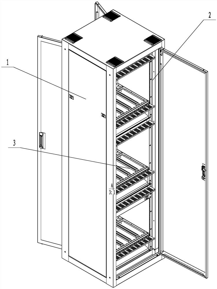
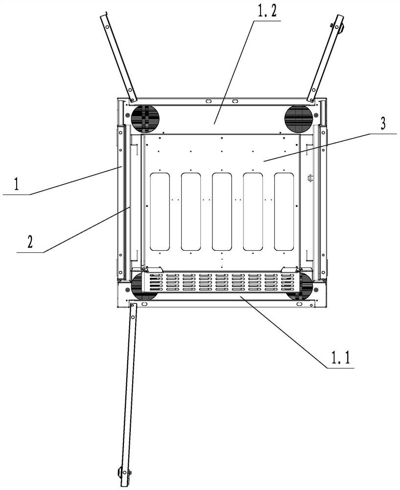
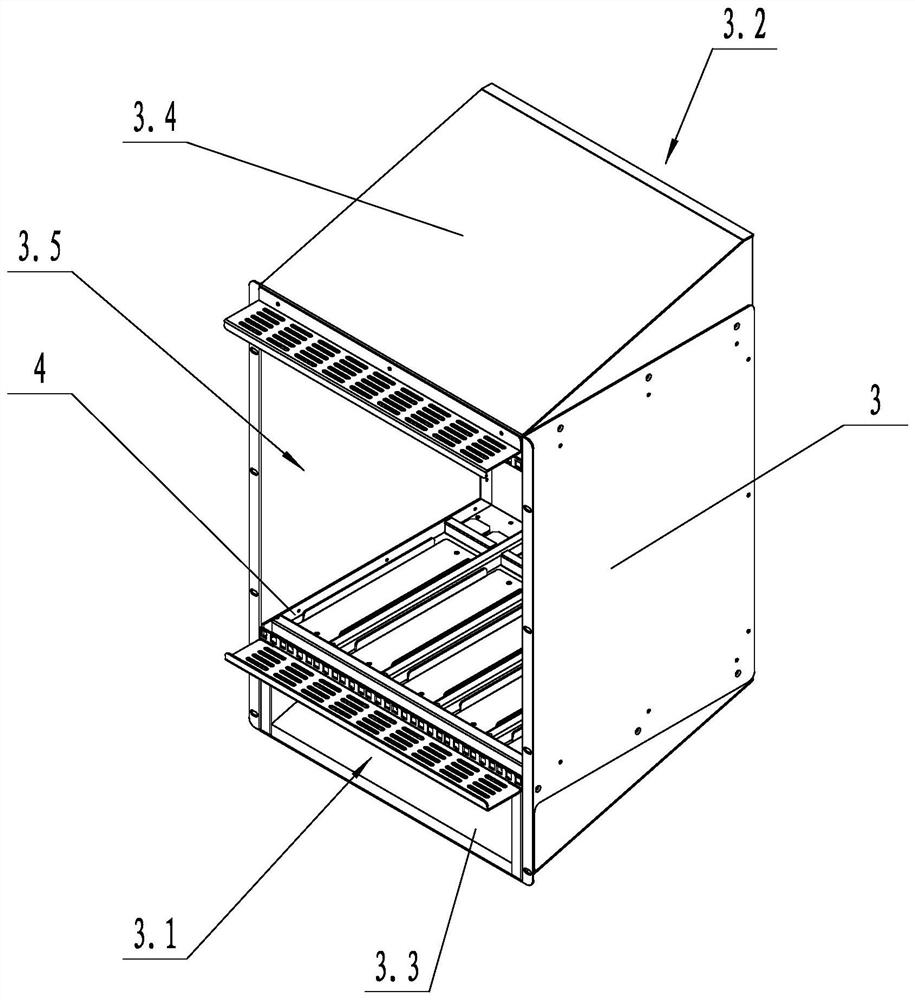
[0028] like figure 1 , figure 2 and image 3As shown, a BBU vertical installation cabinet with good heat dissipation effect includes an outer cabinet 1, a fixing frame 2 and several sub cabinets 3, the fixing frame 2 is arranged in the outer cabinet 1, and several sub cabinets 3 are arranged up and down in order and are fixed with the fixing frame 2 , the sub-cabinet 3 and the fixing frame 2 divide the internal space of the outer cabinet 1 into an air inlet cavity 1.1 and an air outlet cavity 1.2; the lower part of the sub-cabinet 3 is provided with an air inlet 3.1, and the air inlet 3.1 faces the air inlet cavity 1.1. The upper part of 3 is provided with an air outlet 3.2, and the air outlet 3.2 faces the air outlet cavity 1.2. Below the air inlet 3.1 is an air intake guide plate 3.3 arranged obliquely. The air outlet guide plate 3.4 is provided above the air outlet 3.2. The height of the air outlet guide plate 3.4 on the side close to the air inlet cavity 1.1 is lower t...
Embodiment 2
[0031] like Figure 4 As shown, on the basis of Embodiment 1, the side of the bottom sealing plate 5 close to the air inlet cavity 1.1 is hinged with the sub-cabinet 3, the hinge axis axis of the bottom sealing plate 5 is parallel to the arrangement direction of several mounting brackets 4, and the bottom The sealing plate 5 is provided with a spring for making the bottom sealing plate 5 close to the sub-cabinet 3, a lifting block 6 is arranged on the sub-cabinet 3, the lifting block 6 is slidably connected with the sub-cabinet 3, and the lower end of the lifting block 6 is connected to the bottom sealing plate 5. touch. The upper end of the lifting block 6 facing the air inlet cavity 1.1 is provided with a guiding slope 6.1.
[0032] In the above technical solution, the spring may be a telescopic spring or a torsion spring. If the BBU unit is not installed on the mounting bracket 4, the bottom sealing plate 5 presses the bottom of the mounting bracket 4 under the action of ...
Embodiment 3
[0034] like Figure 5 As shown, on the basis of Embodiment 1, one side of the bottom sealing plate 5 is hinged with the sub-cabinet 3, the hinge axis axis of the bottom sealing plate 5 is perpendicular to the arrangement direction of several mounting brackets 4, and the bottom sealing plate 5 is provided with There is a spring for making the bottom sealing plate 5 close to the sub-cabinet 3 . The sub-cabinet 3 is provided with a lifting block 6 , and the lower end of the lifting block 6 is in contact with the bottom sealing plate 5 . The upper end of the lifting block 6 facing the air inlet cavity 1.1 is provided with a guiding slope 6.1.
[0035] In the above technical solution, the spring may be a telescopic spring or a torsion spring. If the BBU unit is not installed on the mounting bracket 4, the bottom sealing plate 5 presses the bottom of the mounting bracket 4 under the action of the spring to make the bottom of the mounting bracket 4 airtight, so as to prevent cold ai...
PUM
 Abstract
Description
Claims
Application Information
 - R&D
- Intellectual Property
- Life Sciences
- Materials
- Tech Scout
- Unparalleled Data Quality
- Higher Quality Content
- 60% Fewer Hallucinations
Browse by: Latest US Patents, China's latest patents, Technical Efficacy Thesaurus, Application Domain, Technology Topic, Popular Technical Reports.
© 2025 PatSnap. All rights reserved.Legal|Privacy policy|Modern Slavery Act Transparency Statement|Sitemap|About US| Contact US: help@patsnap.com


