
Ceramic sheet flatness control device and use method

A ceramic thin plate and control device technology, which is applied in the direction of construction and building construction, can solve the problems of complex installation and inability to effectively control the flatness of ceramic thin plates

Inactive Publication Date: 2021-09-10
CHINA MCC17 GRP
View PDF0 Cites 0 Cited by
  • Summary
  • Abstract
  • Description
  • Claims
  • Application Information

AI Technical Summary

Problems solved by technology

[0004] The technical problem to be solved by the present invention is: the prior art cannot directly and effectively control the flatness of ceramic sheet installation, and the installation is complicated

Method used


Image

  • Ceramic sheet flatness control device and use method
  • Ceramic sheet flatness control device and use method
  • Ceramic sheet flatness control device and use method

Examples


Embodiment 1

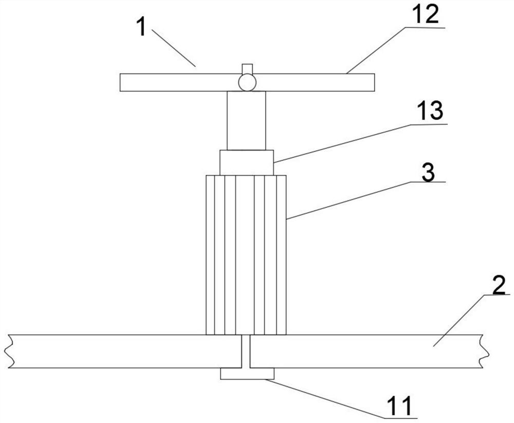
[0036] Such as figure 1 As shown, it is an embodiment of the present invention, a device for controlling the flatness of a thin ceramic plate, including an upper part 1 and a lower sleeve 3, the upper part 1 includes a test strip 11, and the test strip 11 is installed at the lower end of the upper part 1, The test strip 11 is adapted to pass through two sets of ceramic thin plates 2 and be rotated and clamped under the two sets of ceramic thin plates 2;

[0037] The lower sleeve 3 is installed on the upper part 1 and is suitable for rotating against the upper ends of the two sets of ceramic thin plates 2 .

[0038] Further, the upper part 1 includes a handle part 12, the handle part 12 is located at the upper end of the upper part 1, the lower end of the handle part 12 is installed with an upper post 13, the outer surface of the upper post 13 is provided with external threads, and the lower sleeve 3 is provided with an inner thread. thread, the lower sleeve 3 is threadedly co...

Embodiment 2

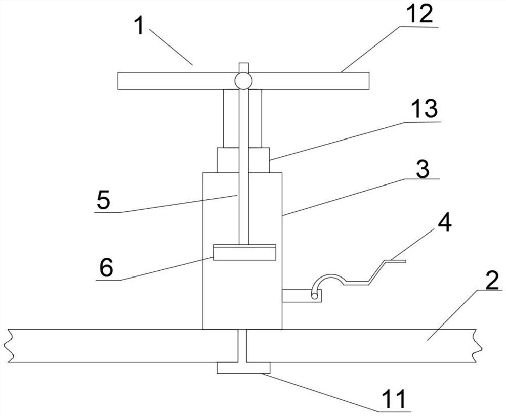
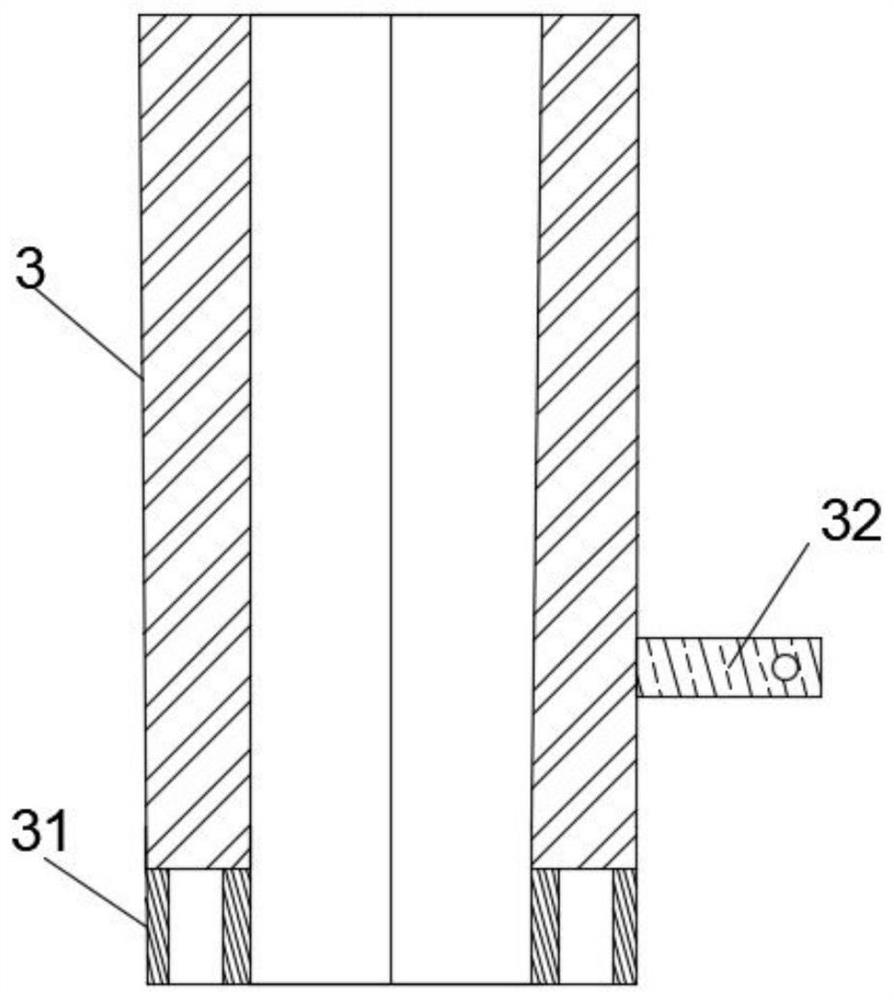
[0042] Such as Figure 2 to Figure 6 Shown is another embodiment of the present invention, on the basis of Example 1, the lower end of the lower sleeve 3 is provided with an annular portion 31, the lower end of the annular portion 31 is arranged horizontally, and the lower end of the annular portion 31 is provided with a cavity , the ring portion 31 is suitable for fitting on the upper ends of the two sets of ceramic thin plates 2 during installation.

[0043] In order to facilitate the installation of construction personnel, when a large number of this device needs to be installed, it is very easy to generate repetitive labor and cause inefficiency. By installing a connecting column 32 outside the lower sleeve 3, the connecting column 32 is provided with a mounting hole, and a rotating shaft is installed in the mounting hole. The wrench 4 is detachably connected to the mounting hole by turning the wrench 4, and the turning wrench 4 is suitable for adjusting the position of th...


PUM


Abstract

The invention discloses a ceramic sheet flatness control device and a use method, and belongs to the field of sheet installation. The ceramic sheet flatness control device comprises an upper part and a lower sleeve, wherein the upper part comprises a test strip, the test strip is installed at the lower end of the upper part, and the test strip is suitable for penetrating through two sets of ceramic sheets and being rotationally clamped below the two sets of ceramic sheets; and the lower sleeve is installed on the upper part and is suitable for being rotationally abutted against the upper ends of the two sets of ceramic sheets. The ceramic sheet flatness control device solves the technical problems that the flatness of the ceramic sheet installation cannot be directly and effectively controlled and the installation is complex in the prior art.

Description

technical field [0001] The invention belongs to the field of thin plate installation, and in particular relates to a ceramic thin plate flatness control device and a use method. Background technique [0002] In the prior art, when laying ceramic plates, adhesives are basically added to the cement. After the strength of the cement increases, a large area of ​​ceramic sheets can be fixed. Secondly, when laying ceramic sheets, tap them with a small leather hammer Hit the ceramic thin plate, and then use the senses to observe the flatness of the thin plate. When the construction area is large, the overall wall flatness is difficult to meet the specification requirements, and the brick joints between two adjacent ceramic thin plates are also reserved based on experience. Can not meet the specification requirements very well. [0003] There is an urgent need for a ceramic thin plate flatness control device and a method of use to solve the above problems. Contents of the inventi...

Claims


Application Information

Patent Timeline
IPC IPC(8): E04F21/18E04F21/06E04F21/16
CPCE04F21/18E04F21/1877E04F21/1838E04F21/06E04F21/16
Inventor 王辛悦陈康胜汪涛阮程峰王艳秋
Owner CHINA MCC17 GRP
Learn More