Power consumption detection method and device, electronic equipment and storage medium

A detection method and power consumption technology, applied in error detection/correction, electrical digital data processing, instruments, etc., can solve problems such as usage, abnormal power consumption of equipment, and failure of main power-consuming devices to enter sleep state

Pending Publication Date: 2021-09-17
BEIJING BYTEDANCE NETWORK TECH CO LTD
0 Cites 0 Cited by

AI-Extracted Technical Summary

Problems solved by technology

However, due to some abnormal problems of the device, some applications will still use the main power consumption device in the low power co...

Method used

[0071] In some embodiments, the power consumption-related quantities can be analyzed for the same or different system versions, so that a more comprehensive analysis of power consumption modules with abnormal power consumption can be realized.
[0073] Exemplarily, the system version information sent by the test terminal is received, and the system version is determined based on the system version information (the test terminal can adjust the system version); for the same system version, the power consumption related quantities of each target power consumption module are counted respectively; Display the change curve of the power consumption related quantity of each target power consumption module with respect to time. In one embodiment, according to the type of the target power consumption module, the variation curves of the power consumption related quantities of each target power consumption module with respect to time can be displayed on different interfaces or in different coordinate systems. For example, the target power-consumin...

Abstract

The embodiment of the invention relates to a power consumption detection method and device, electronic equipment and a storage medium. The method comprises the following steps: monitoring a low power consumption mode state of a test end; when it is monitored that the test end enters the low power consumption mode and/or exits the low power consumption mode, obtaining power consumption behavior data of a target power consumption module; and sending the power consumption behavior data to a data management system, so that the data management system determines a power consumption related quantity based on the power consumption behavior data, and the power consumption related quantity is used for representing whether the power consumption of the target power consumption module is abnormal or not. By adopting the technical scheme, the power consumption module with abnormal power consumption can be analyzed, so that a reliable basis is provided for repairing the abnormal power consumption.

Application Domain

Hardware monitoringEnergy efficient computing

Technology Topic

Real-time computingPower consumption +3

Image

  • Power consumption detection method and device, electronic equipment and storage medium
  • Power consumption detection method and device, electronic equipment and storage medium
  • Power consumption detection method and device, electronic equipment and storage medium

Examples

  • Experimental program(1)

Example Embodiment

[0022] Embodiments of the present disclosure will be described in more detail below with reference to the accompanying drawings. Although certain embodiments of the present disclosure are shown, it is understood that the present disclosure can be implemented in various forms, and should not be construed as being limited to the embodiments set forth herein, and the embodiment is provided for More thorough and completely understood the present disclosure. It should be understood that the accompanying drawings and examples of the present disclosure are for exemplary effects, not to limit the scope of protection of the present disclosure.
[0023] It should be understood that the various steps described in the method embodiments of the present disclosure can be performed in a different order, and / or in parallel. Further, the method embodiment can include additional steps and / or omitted the steps shown. The scope of this disclosure is not limited thereto.
[0024] The term "comprising" as used herein and its deformation is open to include, ie, "including but not limited to". The term "based on" is "at least partially based on". The term "one embodiment" means "at least one embodiment"; the term "another embodiment" means "at least one additional embodiment"; the term "some embodiments" means "at least some embodiments". Related definitions of other terms will be given in the following description.
[0025] It is to be noted that the "first", "second" and other concepts mentioned in the present disclosure are only used to distinguish different devices, modules, or units, are not used to define the order of the functions performed by these devices, modules, or units. Or interdependent relationship.
[0026] It should be noted that "a" "one", "multiple" modifications mentioned in the present disclosure are schematic rather than limiting, and those skilled in the art will appreciate that, unless otherwise clearly indicated in the context, it should be understood as "one or Multiple.
[0027] The name of the interactive message or information between the plurality of devices in the present disclosure is only for illustrative purposes, and is not used to limit the range of these messages or information.
[0028] Normally, when the test machine is in a low power consumption mode, all applications stop using the device resources, the power consumption module. However, some white list applications set by the vendor can still use some power consumption modules, resulting in that part of the power consumption module cannot sleep, causing power consumption problems.
[0029] In order to solve the above problem, the present disclosure provides a power consumption detection method that effectively analyzes power consumption modules based on the power consumption correlation amount obtained by the method. This method is described in conjunction with the specific embodiments.
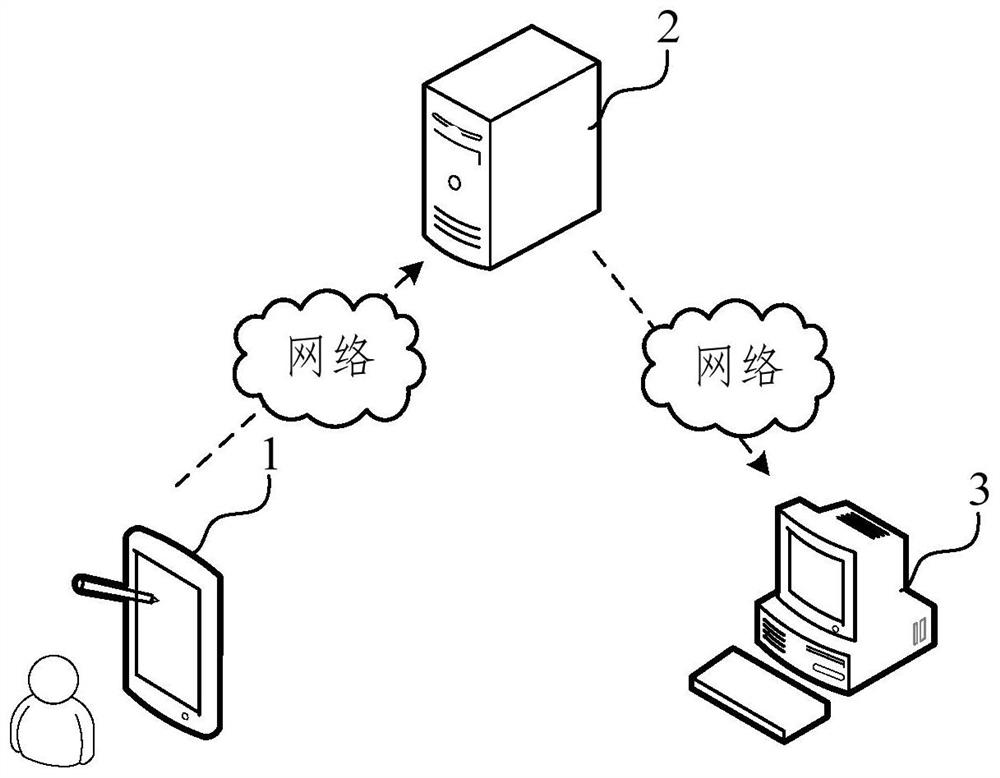
[0030] In some embodiments, the power consumption detection method provided by the embodiment of the present disclosure can be applied to figure 1 The application environment is shown. This power consumption detection method is applied to the power consumption detection system, which includes test end 1, cloud 2, and data processing terminals 3. Wherein, the test terminal 1 communicates with the cloud 2 through the network, and the data processing terminal 3 communicates with the cloud 2 through the network. Test ends 1 include, but are not limited to, various personal computers, laptops, smartphones, tablets, and portable wearable devices, cloud 2 can be a server cluster composed of multiple servers, and data processing terminals 3 can be a computer or the like. Device for data processing functions. In this embodiment, the test terminal 1 monitors the low power consumption mode state of the test end, and when the test end enters the low power consumption mode and / or exits the low power consumption mode, the power consumption behavior data of the target power consumption module will be consumed. The electric row is transmitted to the cloud 2; the cloud 2 stores power consumption behavior data; the data processing terminal 3 acquires power consumption behavior data from the cloud 2, based on power consumption behavior data, determines power consumption correlation amount.
[0031] In some embodiments, the cloud 2 can also determine the power consumption correlation amount based on the power consumption behavior, and the data processing terminal 3 acquires power consumption from the cloud 2.
[0032] In some embodiments, the power consumption detection system can include the above-described test end 1 and the data processing terminal 3 without the cloud 2. At this time, the test terminal 1 transmits the power consumption behavior data directly to the data processing terminal 3, and the data processing terminal 3 determines the power consumption correlation amount based on the power consumption behavior data.
[0033] In some embodiments, the power consumption detection system may include only the test end 1 described above without including the cloud 2 and the data processing terminal 3. At this time, the test terminal 1 acquires the power consumption behavior data of the target power consumption module, and directly determines the power consumption correlation amount based on the power consumption behavior data.
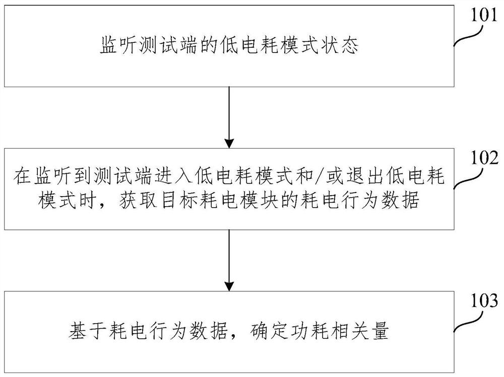
[0034] figure 2 A flow diagram of a power consumption detection method provided in the present disclosure, which is applicable to detecting abnormal power consumption of intelligent electronic devices in the development phase to discover abnormal power consumption. The method can be performed by a power consumption detecting device, wherein the device can be implemented using software and / or hardware, generally integrated in an electronic device. like figure 2 As shown, the method includes:
[0035] Step 101, monitor the low power consumption mode status of the test end.
[0036] Where low power consumption mode state includes entering a low power consumption mode or exiting a low power consumption mode or in a low power consumption mode. After the tester is not inserted, the screen is turned off and in a stationary state, the test machine enters a low power consumption mode, and the low power consumption mode status is updated to enter the low power consumption mode. When the user wakes the test machine by moving the test machine, open the screen or connected to the charger, the system immediately exits the low power consumption mode, and the low power consumption mode status is updated to exit low power consumption mode.
[0037] In some embodiments, the low power consumption mode state can be characterized by low power consumption mode identification. Exemplary, low power consumption mode status corresponds to a low power consumption mode identifier, such as 0 or 1, 0 can represent entering a low power consumption mode, 1 can represent exiting low power consumption mode, the test machine querying the low power consumption mode identification It is possible to determine the low power consumption mode status.
[0038] Step 102, when listening to the test end entering the low power consumption mode and / or exits the low power consumption mode, the power consumption behavior data of the target power consumption module is obtained.
[0039] In the present disclosure, it is possible to determine whether the low power consumption mode can be determined by monitoring whether the low power consumption mode is changed or exiting low power consumption mode, for example, when the low power consumption mode identification is changed from 1 to 0, it is determined The test machine enters a low power consumption mode; when the low power consumption mode identification is changed from 0 to 1, it is determined that the test machine exits the low power consumption mode.
[0040] In the present disclosure embodiment, the target power consumption module can be a sub-system of the test end, or a framework layer device of a test end. Power consumption behavior data refers to data related to power consumption.
[0041] In some embodiments, the target power consumption module includes a sub-system of the test end, and the power consumption behavior data includes a low power consumption mode time and a subsystem sleep time, the low power consumption mode time, the tester is in a low power consumption mode.
[0042]Accordingly, in listening to the end of the test to enter low-power mode and / or when to exit the low power consumption mode, the power consumption behavior data acquisition target power module, comprising:
[0043] Step 1021, when listening to the test terminal enters a low power consumption mode, a first recording time to enter low-power mode.
[0044] Based on the above embodiment, the low power consumption mode update timing may be used as the time to enter low-power mode, or to exit the low power consumption mode. For example, when the low power consumption mode state update when entering low-power mode, the status update time as a first time to enter low-power mode, the first time recording.
[0045] Step 1022, when listening to the end of the test to exit the low power consumption mode, the second record timing when exiting low power consumption mode, and the sleep time data acquisition subsystem by subsystem associated node reads.
[0046] Similar records a first time may be updated when exiting a low power consumption mode, the status update time in the low power consumption mode state as the second time when the low power consumption exit mode, to record the second time.
[0047] In some embodiments, the subsystem comprising: an application processor subsystem, the modem processor subsystem, audio digital signal processing subsystem, calculates the digital signal processing subsystem and the sensor subsystem in low power island of at least one. In the disclosed embodiment of the present embodiment, the sleep time data is recorded in the associated subsystem subsystem node, exemplary, read node: / sys / power / system_sleep / stats, available application processor subsystem, a modem processor subsystem, audio digital signal processing subsystem calculates the sleep time data digital signal processing subsystem and the sensor subsystem in low power island of the at least one subsystem. It should be noted that the sleep time data is data corresponding to the sleep time between the first time and the second time point.
[0048] Further, subsystem may further include wifi (wireless network), taking into account the wifi sleep time data recording node does not exist, the sleep time data may be acquired by wifi dumpwifi sleep state.
[0049] Step 1023, based on the difference between the second time and the first time, the low-power mode determination time, the time data is determined based on sleep and sleep subsystem.
[0050] In this embodiment, the second time is the low-power mode by subtracting a second time period; sleep time after acquiring the data, the data is converted to the sleep subsystem seconds to obtain sleep. It will be appreciated that the greater the sleep mode with low power consumption times the ratio, the better the effect of sleep subsystem, subsystem power the more normal.
[0051] In some embodiments, the target module includes a power framework layer test device side, power switch state behavior data comprises use of the device and the frame layer state corresponding GPIO pins.
[0052] Accordingly, in listening to the end of the test to enter low-power mode and / or when to exit the low power consumption mode, the power consumption behavior data acquisition target power module, comprising:
[0053] Step 1021 ', when listening to the test mode terminal enters or exits the low-power low-power mode, reads the feedback data used to characterize the state of use, general-purpose input and acquired by reading the GPIO pins or chip associated node switch state data output pin.
[0054] In some embodiments, the frame power device hardware layer device, the frame layer device having a general purpose input-output pins one relationship. Optionally, the apparatus includes a screen frame layer, a light emitting diode front, rear light-emitting diode, flash lamp, and at least one earphone.
[0055] Normally, the feedback data and switch status data homogeneous match at any time, i.e., using the same are reflected in the frame layer device state. However, where an abnormal state of the apparatus frame layer (abnormal power equivalent), the feedback data and switch status data not match, i.e., the frame layer reflects a different state of use of the device.
[0056] Exemplary, when the frame layer device is a screen, the screen at the time of turning on and off will issue a broadcast system based on a broadcast recording current screen state (on or off), i.e. the feedback data, the feedback data may be 0 or 1 Express. Corresponding to the general purpose input output pins or chip associated node records the switching state of GPIO pin data, switch status data which can be represented by 0 or 1. When the frame for the front-layer device or a light emitting diode rear light-emitting diode is lit call noteFlashlightOn front rear light-emitting diode or a light emitting diode, the current record at this time may be a light emitting diode or a light emitting state of the front rear light-emitting diode, i.e., feedback data, the feedback data can be represented by 1; noteFlashlightOff call off when the light emitting diode front or rear light-emitting diode, the current record at this time may be a light emitting diode or a light emitting state of the front rear light-emitting diode, i.e. the feedback data, the feedback data It can be expressed as zero.
[0057] Step 1022 ', based on feedback data used to determine the status and switch status data is determined based on the switch state.
[0058] Exemplary feedback data comprise 0 or 1, when the feedback data is 0, the state of use of the device using the frame layer, such as a screen lighting, front or rear emitting diode LED lights, turn on the flash or the like is inserted into the headphone ; when the feedback data is 1, the state of the device frame layer is not used, such as screen off, front or rear light-emitting diode LED is off, flash off unplug the headset or the like. Switch state data includes 0 or 1, when the switch state data is 0, the switch status is turned off; when the switch status data is 1, the switch to ON.
[0059] Step 103, based on consumption behavior data, determining power-related quantity.
[0060] In one embodiment of the present embodiment, the test machine in real time the consumption behavior data uploaded to the cloud, i.e. testing machine behavior data is acquired after the power consumption behavior data uploaded to the cloud; Alternatively, timing may tester after consumption behavior data uploaded to the cloud, for example, each tester consumption behavior data is acquired, the power consumption behavior data cache, when a preset time (e.g. one day), to obtain the preset time of All-time consumption behavior data uploaded to the cloud. Corresponding to the data processing terminal may be acquired in real time from the cloud consumption behavior data uploaded test machine, or the data processing terminal can acquire the timing of power testing machine behavior data uploaded from the cloud. In another embodiment of the present embodiment, the power test machine behavior data to the cloud; based on consumption behavior data via a cloud, the power consumption related quantity determined. Thereafter, the data processing terminal can acquire power related quantity from the cloud.
[0061] Disclosure of the present embodiment, the power-related quantity for characterizing a target power consumption of the module is abnormal.
[0062] In some embodiments, the target module includes a power subsystem test terminal, the power consumption behavior data comprises a low-power mode and subsystems sleep time.
[0063] Accordingly, the power consumption based on behavior data, determining power-related quantity, comprising:
[0064] The subsystem ratio of sleep duration and low power consumption mode time as a percentage of sleep subsystem, the subsystem for the percentage of sleep related to power consumption amount.
[0065] In some embodiments, an amount of power related to the percentage of sleep subsystem, i.e. subsystem sleep duration and low-power mode time ratio. Typically, when the sleep subsystem percentage equal to or greater than a threshold percentage of sleep (e.g. 95%), the subsystem power can be determined properly; when the percentage is less than the sleep subsystem sleep threshold percentage (e.g. 95%) can be determined sub power system anomalies.
[0066] In some embodiments, the target module includes a power framework layer test device side, power switch state behavior data comprises use of the device and the frame layer state corresponding GPIO pins.
[0067] Accordingly, the power consumption based on behavior data, determining power-related quantity, comprising:
[0068] The use state of the switching state of the match, to obtain the degree of match between the input and output pins universal framework layer corresponding device, power consumption is related quantity matching degree.
[0069] In some embodiments, the matching degree comprises a match or mismatch. An amount of consumption related degree of match between the GPIO pins with the corresponding frame layer device, i.e., device usage state of the frame layer and the GPIO pins switch state corresponding match. Exemplary, use state and the device layer frame corresponding to the state of the switch GPIO pin having a preset correspondence relationship. If the frame state using the switch state and a corresponding device layer GPIO pin satisfies a predetermined correspondence relationship, the usage state of the frame layer device matches the switching state of the GPIO pins corresponding to, i.e., the frame layer device and GPIO pins corresponding match, the device may determine that the frame layer normal power; otherwise, the state of the device layer frame corresponding to the state of the switch GPIO pins do not match, i.e. universal input device and corresponding to the frame layer output pins do not match, the device may determine that the frame layer abnormal power consumption.
[0070] Embodiment of the present disclosure power detection solution provided by the trigger when the low power consumption mode state, the power consumption behavior data acquisition target power module, the power consumption based on behavior data, characterizing a target power determined for the power module whether abnormal power related quantity, which can analyze the abnormal power consumption module, provides a reliable basis for abnormalities related to power consumption based on the power consumption amount of repair.
[0071] In some embodiments, the power consumption can be analyzed for the relevant amounts of the same or different versions of the system, so that power consumption can be realized on abnormal power consumption of a more comprehensive analysis module.
[0072] In some embodiments, the power consumption based on behavior data after determining power-related quantity detecting method may further include the power consumption: for the same version of the system, certain statistics related to power consumption amount of the power consumption module; target power consumption display module power curve related quantity with respect to time.
[0073] Exemplary system version information, the receiving end sends the test, the version information determination system based on the system version (test terminal adjustable version); version for the same system, statistics related to power consumption amounts of the respective target power module; show each object power consumption module related quantity change curve with respect to time. In one embodiment, the target power may be module type, showing power consumption of each target module related quantity change curve with respect to time or at different interfaces different coordinate systems. For example, the target power module according to the type and the frame can be divided into sub-layer devices, all power subsystems related quantity curve with respect to time is shown in the first interface or the first coordinate system, and all devices work frame layer Related consumption amount curve with respect to time or the second interface is shown in the second coordinate system, the first interface and the second interface are different interfaces, a first coordinate system and the second coordinate systems are different coordinate systems. Thus, statistics related to power consumption by the target power module, the power consumption can avoid misjudgment of abnormality caused by a single data error, improve the accuracy of the determination of the abnormal power consumption, at the same time, the contrast can be more intuitively same abnormal power consumption of the system module version.
[0074] In some embodiments, the power consumption based on behavior data after determining power-related quantity detecting method may further include the power consumption: for different versions of the system, the amount of power consumption targets are statistically relevant power module; target power consumption display module the amount of curve on power-related system version.
[0075]Exemplary system version information, the receiving end sends the test, the version information determination system based on the system version (test terminal adjustable version); versions for different systems, respectively, statistics related to power consumption amount of each target power module; show each object power consumption module related quantity change curve regarding system version. Examples curve shows the amount of power-related manner on the system version of the present embodiment, the display manner may be the same power related quantity change curve in the above-described embodiment with respect to time, it is not repeated here. Thus, it can be seen visually affect the system upgrade, power modules or power recession.
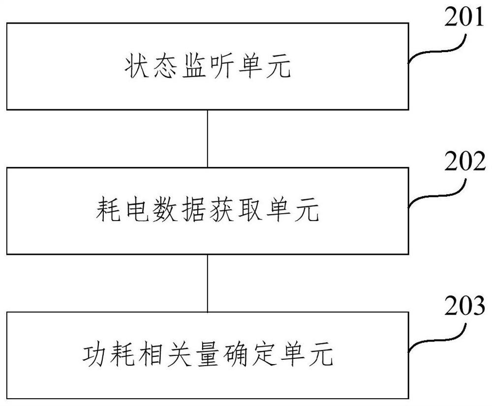
[0076] image 3 A schematic structure of a power consumption detecting apparatus according to an embodiment of the present disclosure, the apparatus may be software and / or hardware implementations, and can be integrated in an electronic device. like image 3 As shown, the apparatus includes:
[0077] State monitoring unit 201, a low-power mode state monitor test terminal;
[0078] Power consumption data acquisition unit 202, a test terminal for monitoring a low-power mode and enter or / exit a low power consumption mode, the power consumption acquiring data of the target behavior of the power module;
[0079] Related power amount determination unit 203, based on consumption behavior data, to determine the amount of power-related, power related quantity for characterizing a target power consumption of the module is abnormal.
[0080] In some embodiments, the target module includes a power subsystem end of the test, the power consumption behavior data comprises a low-power mode and the sub-time sleep;
[0081] Power consumption data acquisition unit 202 is specifically configured to:
[0082] When listening to the test terminal enters a low power consumption mode, a first recording time to enter low-power mode;
[0083] A second time when the test terminal when listening to exit the low power consumption mode, a recording mode to exit the low power consumption, and sleep time data acquisition subsystem by subsystem reads the relevant node;
[0084] Based on the difference between the first time and the second time, the low-power mode determination time, the time data is determined based on sleep and sleep subsystem.
[0085] In some embodiments, the subsystem comprising: an application processor subsystem, the modem processor subsystem, audio digital signal processing subsystem, calculates the digital signal processing subsystem and the sensor subsystem in low power island of at least one.
[0086] In some embodiments, power-related quantity determining unit 203 is specifically configured to:
[0087] The subsystem ratio of sleep duration and low power consumption mode time as a percentage of sleep subsystem, the subsystem for the percentage of sleep related to power consumption amount.
[0088] In some embodiments, the target module includes a power framework layer test device terminal, the power consumption state behavior data comprises using the frame layer and a corresponding device universal input switching state output pins;
[0089] Power consumption data acquisition unit 202 is specifically configured to:
[0090] When listening to the test mode terminal enters or exits the low-power low-power mode, for reading the feedback data used to characterize the state and acquires GPIO pin GPIO pins by reading the relevant node or chips switch state data;
[0091] Determine based on the feedback data state and the state data is determined based on the switching state of the switch.
[0092] In some embodiments, the apparatus includes a screen frame layer, a light emitting diode front, rear light-emitting diode, flash lamp, and at least one earphone.
[0093] In some embodiments, power-related quantity determining unit 203 is specifically configured to:
[0094] The use state of the switching state of the match, to obtain the degree of match between the input and output pins universal framework layer corresponding device, power consumption is related quantity matching degree.
[0095] In some embodiments, the power consumption detecting apparatus further comprising: a power-related quantity statistics unit, based on the power consumption for the behavior data, after determining the amount of power-related, related to the same system for power version, the target power consumption statistics module volume; or,
[0096] For different system versions, respectively, statistics related to the amount of power consumption target module.
[0097] In some embodiments, the power consumption detecting apparatus further comprising: a display unit configured for the same system after release, the statistical target power consumption amount related module, display module power consumption target related quantity changes with respect to time curve; or
[0098] After different system versions, respectively, related to the amount of target power consumption statistics module, showing the power consumption related to the amount of the target module curve on system version.
[0099] In some embodiments, power-related quantity determining unit configured to:
[0100] The behavior of the power consumption data to the cloud;
[0101] Drive power based on behavior data via a determined quantity related to power consumption.
[0102] Power detecting means provided in the embodiment of the present disclosure of the present disclosure may perform power detection method corresponding to the embodiment provided, the method comprising performing a respective function module and benefits.
[0103] Example embodiments of the present disclosure further provides a computer program product, comprising computer program / instruction steps of the present disclosure to any power detection method according to an embodiment of the realization of a processor when executed by the computer program / instruction.
[0104] Figure 4 A structural diagram of an electronic device provided by the embodiment of the present disclosure.
[0105] The following specific reference Figure 4 Which shows a schematic structural diagram suitable for implementing the present embodiment of the electronic device 300 disclosed embodiments. The present disclosed embodiment the electronic device 300 embodiments may include but are not limited to, such as mobile phones, notebook computers, digital broadcast receiver, PDA (personal digital assistant), the PAD (tablet), the PMP (portable multimedia player), in-vehicle terminal ( such as a car navigation terminal) like a mobile terminal such as a digital TV, a desktop computer and the like fixed terminal. Figure 4 The illustrated electronic device is merely an example, and there is no limit to the function and the range of use of the present disclosure.
[0106] like Figure 4 Shown, the electronic device 300 may include a processing device (such as a central processor, a graphics processor, etc.) 301, which may or load 302 in accordance with a program stored in a read only memory (ROM) 308 from a storage device into a random access memory (RAM ) 303 executes various program and appropriate action process. In the RAM 303 also stores various programs and data necessary for operation of the electronic device 300. Processing means 301, ROM 302 and RAM303 are connected through a bus 304. Input / Output (I / O) interface 305 is also connected to the bus 304.
[0107] Typically, the device may be connected to the I / O interface 305 include: such as a touch screen, touch pad, keyboard, mouse, camera, microphone, accelerometer, gyroscope, etc. The input device 306; includes a liquid crystal display (LCD), a speaker, a vibration the output device 307 or the like; for example, include a magnetic tape, a hard disk storage device 308; and a communication device 309. The communication device 309 may allow the electronic device 300 perform wireless or wired communication with other devices to exchange data. Although Figure 4 Shows an electronic device 300 having various devices, it should be appreciated that the embodiment does not require or have all of the devices shown. More or fewer devices can be replaced or more or less.
[0108] In particular, according to the embodiment of the present disclosure, the process described above can be implemented as a computer software program. For example, an embodiment of the present disclosure includes a computer program product comprising a computer program carrying a non-transitory computer readable medium, which includes program code for performing a flowchart. In such an embodiment, the computer program may be downloaded via the communication device 309 from the network and installed, or is installed from a storage device 308, or mounted from the ROM 302. When the computer program is executed processing apparatus 301 performing the above-described embodiment of the present disclosure function of the power consumption detection method defined.
[0109] It should be noted that the computer readable medium of the present disclosure may be a computer readable signal medium or a computer readable storage medium or an arbitrary combination of the above. The computer readable storage medium is, for example, - but is not limited to, system, magnetic, light, electromagnetic, infrared, or semiconductor, or means, or any combination of any more. More specific examples of computer readable storage media can include, but are not limited to, electrical connections having one or more wires, portable computer disks, hard disks, random access memory (RAM), read-only memory (ROM), flaky Programmable read-only memory (EPROM or flash), fiber, portable compact disk read only memory (CD-ROM), optical storage device, magnetic storage device, or any suitable combination of the above. In the present disclosure, the computer readable storage medium can be any tangible medium comprising or stored programs, which can be used instruction execution system, device, or device or in combination thereof. In the present disclosure, the computer readable signal medium can include a data signal propagating in a baseband or as part of a carrier, wherein the computer readable program code is carried. Such propagation data signals can be used in a variety of forms, including, but not limited to, electromagnetic signals, optical signals, or any suitable combination of the above. The computer readable signal medium may also be any computer readable medium other than the computer readable storage medium, which can transmit, propagate, or transmit a program for use by instruction execution system, device, or device or in combination thereof. . The program code included on the computer readable medium can be transmitted with any suitable media, including, but not limited to, wires, optical cables, RF (RF (RF), or the like, or any suitable combination of the above.
[0110] In some embodiments, the client, the server can communicate with any currently known or future-developed network protocol, such as HTTP (Hypertext TransferProtocol, hypertext transfer protocol), and can communicate with any form or media (Eg, communication network) interconnect. Examples of the communication network include local area network ("LAN"), WAN ("WAN"), Internet (eg, internet) and end-to-end networks (eg, an AD HOC-end-to-end network), and any currently known or future development network of.
[0111] The above computer readable medium can be included in the electronic device; may also be alone without mating in the electronic device.
[0112] Said computer-readable medium carrying one or more programs, when the one or more programs executed by the electronic device, so that the electronic device: listening Doze state of the test terminal; enters a low power consumption in a listening test to end mode and / or exit a low power consumption mode, obtaining the target power consumption behavior data module; based on consumption behavior data, to determine the amount of power-related, power related quantity for characterizing a target power consumption of the module is abnormal .
[0113]A computer program code for performing the operation of the present disclosure can be written in one or more programming languages ​​or a combination, including but not limited to object-oriented programming languages ​​- such as Java, SmallTalk, C ++, Includes conventional process programming languages ​​- such as "C" or similar programming languages. The program code can be performed completely on the user's computer, partially executed on the user's computer, execute as a separate package, partially performed on the remote computer on the remote computer, or on the remote computer or server. In the case of a remote computer, the remote computer can be connected to the user computer by any kind of network, including a local area network (LAN) or a wide area network (WAN), or can be connected to an external computer (eg, using the Internet service provider. Internet connection).
[0114] The flowcharts and block diagrams in the drawings illustrate the system architecture, function, and operation of the system, method, and computer program products in accordance with various embodiments of the present disclosure. In this regard, each of the flowcharts or block diagrams can represent a portion of a module, block, or code, one of the modules, blocks, or code contains one or more logical functions for implementing predetermined logic functions. Executive instructions. It should also be noted that in some implementations of the substitution, the functions labeled in the box can also occur in the order of different from the drawings. For example, two coupled blocks can actually be performed substantially in parallel, and they can sometimes be performed in reverse order, which is determined according to the functions involved. It is also important to note that each block in block diagram and / or flowchart, and a combination of boxes in block diagrams and / or flowcharts, you can implement a dedicated hardware-based system that performs predetermined functions or operations. Or can be implemented with a combination of dedicated hardware to computer instructions.
[0115] The units described in the embodiments described in the present disclosure can be implemented in the manner of software, or can be implemented by hardware. Wherein, the name of the unit does not constitute a limit on the unit itself in some cases.
[0116] The functions described above in this article can be performed at least partially by one or more hardware logic components. For example, non-limiting, the hardware logic components of the exemplary types that can be used include: field programmable gate array (FPGA), dedicated integrated circuit (ASIC), special standard product (ASSP), on-chip system (SOC), complex programmable programmable Logic device (CPLD), etc.
[0117] In the context of the present disclosure, the machine readable medium may be a tangible medium, which may contain or store procedures for instruction execution systems, devices, or devices, or using instruction execution systems, devices, or devices. The machine readable medium can be a machine readable signal medium or a machine readable storage medium. Machine readable media can include, but are not limited to, electron, magnetic, optical, electromagnetic, infrared, or semiconductor systems, devices, or any suitable combination of the above. More specific examples of machine readable storage media include electrical connection, portable computer disc, hard disk, random access memory (RAM), read-only memory (ROM) based on one or more lines of electrical connection, read-only memory (ROM), can be programmable read-only memory (EPROM or flash memory), fiber optic, convenient compact disk read only memory (CD-ROM), optical storage device, magnetic storage device, or any suitable combination of the above.
[0118] According to one or more embodiments of the present disclosure, the present disclosure provides a method of power consumption detection, including:
[0119] Monitor the low power consumption mode status of the test end;
[0120] When listening to the test end entering the low power consumption mode and / or exits the low power consumption mode, the power consumption behavior data of the target power consumption module is obtained;
[0121] Based on the power consumption behavior data, the power consumption is determined, and the power consumption correlation amount is used to characterize whether the power consumption of the target power consumption module is abnormal.
[0122] In accordance with one or more embodiments of the present disclosure, in the power consumption detection method provided by the present disclosure, the target power consumption module includes a subsystem of the test end, the power consumption behavior data including a low power consumption mode time and the Summary time;
[0123] When listening to the test end entering the low power consumption mode and / or exits the low power consumption mode, the power consumption behavior data of the target power consumption module includes:
[0124] When listening to the test end entering a low power consumption mode, the first time when the low power consumption mode is recorded;
[0125] When listening to the test end exits the low power consumption mode, the second time when exiting the low power consumption mode is recorded, and the sleep time data of the subsystem is acquired by reading the associated node of the subsystem;
[0126] The low power consumption mode time is determined based on the difference between the second time and the first time, and the sleep time of the subsystem is determined based on the sleep time data.
[0127] According to one or more embodiments of the present disclosure, in the power consumption detection method provided by the present disclosure, the subsystem includes: an application processor subsystem, a modulation processor subsystem, an audio digital signal processing subsystem, a calculation number The signal processing subsystem and at least one of the low power island system in the sensor.
[0128] In accordance with one or more embodiments of the present disclosure, in the power consumption detection method provided by the present disclosure, the power consumption is determined based on the power consumption behavior data, including:
[0129] The ratio of the sleep time of the subsystem to the low power consumption mode time as the sleep percentage of the subsystem, the sleep percentage of the subsystem is the amount of power consumption.
[0130] According to one or more embodiments of the present disclosure, in the power consumption detection method provided by the present disclosure, the target power consumption module includes a frame layer apparatus of the test end, the power consumption behavior data including the framework device. Status and corresponding general purpose input output pin switch status;
[0131] When listening to the test end entering the low power consumption mode and / or exits the low power consumption mode, the power consumption behavior data of the target power consumption module includes:
[0132] When listening to the test end entering a low power consumption mode or exiting the low power consumption mode, feedback data for characterizing the usage state is read, and acquired by reading the associated node or chip of the general input output pin. The switch state data of the general input output pin;
[0133] The use state is determined based on the feedback data, and the switch status is determined based on the switch status data.
[0134] In accordance with one or more embodiments of the present disclosure, in the power consumption detection method provided in the present disclosure, the frame layer device includes at least one of a screen, a front light emitting diode, a rear light-emitting diode, a flash, and a headset.
[0135] In accordance with one or more embodiments of the present disclosure, in the power consumption detection method provided by the present disclosure, the power consumption is determined based on the power consumption behavior data, including:
[0136] The use state is matched to the switch state to obtain a matching degree between the frame layer device and the corresponding general purpose input and output pins, the matching degree of the power consumption.
[0137] In accordance with one or more embodiments of the present disclosure, in the power consumption detection method provided by the present disclosure, the method is also determined based on the power consumption correlation amount, and the method further includes:
[0138] Statard the power consumption of the target power consumption module for the same system; or,
[0139] Statard the power consumption of the target power consumption module for different system versions.
[0140] In accordance with one or more embodiments of the present disclosure, in the power consumption detection method provided by the present disclosure,
[0141] After statistics of the power consumption of the target power consumption module, the method also includes:
[0142] Show the power consumption of the target power consumption module with respect to time change curve; or,
[0143] After the power consumption of the target power consumption module is statistically, the method is also included in different system versions, the method also includes:
[0144] The power consumption of the target power consumption module is shown on the change curve of the system version.
[0145] In accordance with one or more embodiments of the present disclosure, in the power consumption detection method provided by the present disclosure,
[0146] Based on the power consumption behavior data, the power consumption is determined, including:
[0147] Send the power behavior data to the cloud;
[0148] The power consumption correlation amount is determined based on the power-consuming behavior data via the cloud.
[0149] According to one or more embodiments of the present disclosure, the present disclosure provides a power consumption detecting device, including:
[0150] Status listening unit is used to listen to the low power consumption mode status of the test end;
[0151] The power consumption data acquisition unit is used to obtain the power consumption behavior data of the target power consumption module when listening to the test end entering the low power consumption mode and / or exits the low power consumption mode;
[0152] The power consumption correlation amount determining unit is used to determine the power consumption correlation amount based on the power consumption behavior data, which is used to characterize whether the power consumption of the target power consumption module is abnormal.
[0153] According to one or more embodiments of the present disclosure, in the power consumption detecting device provided by the present disclosure, the target power consumption module includes a subsystem of the test end, the power consumption behavior data including a low power consumption mode time and the Summary time;
[0154] The power consumption data acquisition unit is specifically used for:
[0155] When listening to the test end entering a low power consumption mode, the first time when the low power consumption mode is recorded;
[0156] When listening to the test end exits the low power consumption mode, the second time when exiting the low power consumption mode is recorded, and the sleep time data of the subsystem is acquired by reading the associated node of the subsystem;
[0157] The low power consumption mode time is determined based on the difference between the second time and the first time, and the sleep time of the subsystem is determined based on the sleep time data.
[0158] According to one or more embodiments of the present disclosure, in the power consumption detecting apparatus provided by the present disclosure, the subsystem includes: an application processor subsystem, a modulation processor subsystem, an audio digital signal processing subsystem, a calculation number The signal processing subsystem and at least one of the low power island system in the sensor.
[0159] According to one or more embodiments of the present disclosure, in the power consumption detection device provided by the present disclosure, the power consumption correlation amount determination unit is specifically used for:
[0160] The ratio of the sleep time of the subsystem to the low power consumption mode time as the sleep percentage of the subsystem, the sleep percentage of the subsystem is the amount of power consumption.
[0161]According to one or more embodiments of the present disclosure, in the power consumption detecting device provided by the present disclosure, the target power consumption module includes a frame layer apparatus of the test end, the power consumption behavior data including the framework layer device. Status and corresponding general purpose input output pin switch status;
[0162] The power consumption data acquisition unit is specifically used for:
[0163] When listening to the test end entering a low power consumption mode or exiting the low power consumption mode, feedback data for characterizing the usage state is read, and acquired by reading the associated node or chip of the general input output pin. The switch state data of the general input output pin;
[0164] The use state is determined based on the feedback data, and the switch status is determined based on the switch status data.
[0165] In accordance with one or more embodiments of the present disclosure, in the power consumption detecting apparatus provided by the present disclosure, the frame layer apparatus includes at least one of a screen, a front light emitting diode, a rear lighting diode, a flash, and a headset.
[0166] According to one or more embodiments of the present disclosure, in the power consumption detection device provided by the present disclosure, the power consumption correlation amount determination unit is specifically used for:
[0167] The use state is matched to the switch state to obtain a matching degree between the frame layer device and the corresponding general purpose input and output pins, the matching degree of the power consumption.
[0168] According to one or more embodiments of the present disclosure, in the power consumption detecting apparatus provided by the present disclosure, the power consumption detecting device further includes: power consumption-related amount statistical unit for determining power consumption correlation based on the power consumption behavior data After the amount, the power consumption of the target power consumption module is statistically for the same system version; or,
[0169] Statard the power consumption of the target power consumption module for different system versions.
[0170] According to one or more embodiments of the present disclosure, in the power consumption detecting device provided by the present disclosure, the power consumption detecting device further includes: a display unit for statistics of the power consumption module of the target power consumption module in the same system version. After the amount, the power consumption of the target power consumption module is displayed about the time change curve; or,
[0171] After the power consumption of the target power consumption module, the power consumption of the target power consumption module is shown on the system version of the system version.
[0172] According to one or more embodiments of the present disclosure, in the power consumption detection device provided by the present disclosure, the power consumption correlation amount determination unit is specifically used for:
[0173] Send the power behavior data to the cloud;
[0174] The power consumption correlation amount is determined based on the power-consuming behavior data via the cloud.
[0175] According to one or more embodiments of the present disclosure, the present disclosure provides an electronic device, including:
[0176] processor;
[0177] Memory for storing the processor executable instructions;
[0178] The processor is configured to read the executable instruction from the memory and perform the instruction to implement the power consumption detection method as described in the present disclosure.
[0179] According to one or more embodiments of the present disclosure, the present disclosure provides a computer readable storage medium, the storage medium stores a computer program, the computer program for performing any of the present disclosure. Test method.
[0180] The preferred embodiments of the present disclosure and description of the techniques used in the present disclosure are described above. Those skilled in the art will appreciate that the disclosure range according to the present disclosure is not limited to a specific combination of the technical features, and should also be included in the case where the above disclosure is not depressed, or by the above technical characteristics or Other technical solutions formed by equivalent feature of any combination. For example, the above feature is formed with a technical scheme formed by a technicia that is disclosed in the present disclosure (but not limited to) having similar functions.
[0181] In addition, although each operation is depicted in a particular order, this is not to be understood to require these operations to be performed in a specific order or in order order. In a certain environment, multitasking and parallel processing may be advantageous. Likewise, although several specific implementations are included in the above discussion, these should not be construed as limiting the scope of the present disclosure. Some features described in the context of separate embodiments can also be implemented in a single embodiment. Conversely, various features described in the context of a single embodiment may be implemented in a plurality of embodiments separately or in any suitable sub-combination.
[0182] Although this topic has been described in terms of structural features and / or method logic actions, it is understood that the subject matter defined in the appended claims is not necessarily limited to the specific features or operations described above. In contrast, the specific features and operations described above are merely an example form of the claims.

PUM

no PUM

Description & Claims & Application Information

We can also present the details of the Description, Claims and Application information to help users get a comprehensive understanding of the technical details of the patent, such as background art, summary of invention, brief description of drawings, description of embodiments, and other original content. On the other hand, users can also determine the specific scope of protection of the technology through the list of claims; as well as understand the changes in the life cycle of the technology with the presentation of the patent timeline. Login to view more.
Why Eureka
Try Eureka