a bird repellent

A bird repellent and bird repellent technology, applied in the installation and application of animal repellants and cables, can solve the problems of hidden dangers in safe operation, detachment of the installation handle from the insulating ceramic body, and affecting the safe and stable operation of power lines, etc., to achieve Improve the interference of birds, complex movement forms, and maintain the effect of repelling birds

Active Publication Date: 2022-03-22
STATE GRID ZHEJIANG JIASHAN POWER SUPPLY CO LTD
View PDF7 Cites 2 Cited by
  • Summary
  • Abstract
  • Description
  • Claims
  • Application Information

AI Technical Summary

Problems solved by technology

[0002] The joint between the installation handle and the insulating ceramic of the electric power liner is connected by pouring special cement or similar filling materials into the hole of the insulating ceramic body and then inserting the installation handle. Generally, after eight to ten years of installation and use of the electric liner, The aging of the cement filled inside will cause the installation handle and the insulating ceramic body to separate, causing the gram to fall off and form a single-phase grounding of the power line. Gram on
At the same time, as the environment changes, more and more birds are nesting on the power line towers. When birds nest on the upper cross-arm or the cross-arm position, the branches are easy to touch the charged rods. When it rains, power faults such as single-phase grounding or phase-to-phase short circuit will occur, seriously affecting the safe and stable operation of power lines.
[0003] The disadvantage of the common repelling bird repellents now is that the birds will soon adapt to driving through intimidation, sound waves, and a single way of swaying, making the initial bird repellent effect good, but as the birds change the bird repellent habit, will soon reacclimate to the bird repellent
It has the disadvantages of driving regularity and being easily used by birds

Method used


Image

  • a bird repellent
  • a bird repellent
  • a bird repellent

Examples


Embodiment

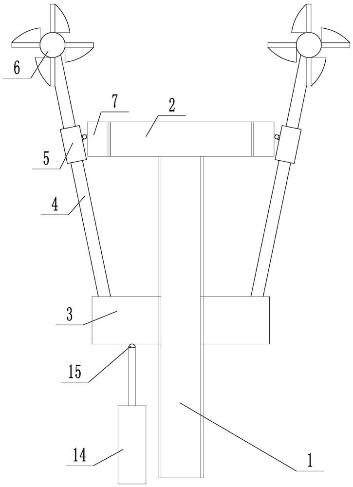
[0030] A bird repellent, such as figure 1 As shown, it includes a threaded shaft 1, a top frame 2 connected to the top of the threaded shaft 1, a threaded disk 3 threaded on the threaded shaft 1, a driving part and a bird-repelling rod body 4, the top frame 2 is rotationally connected with the threaded shaft 1, and the top frame 2 is connected to the threaded shaft 1 in rotation. The outer edge of the frame 2 is provided with a rotating ring 7 that rotates coaxially with respect to the top frame 2, and the positioning sleeve 5 is rotatably connected to the rotating ring 7. The direction is that the shaft swings up and down. The outer edge of the top frame 2 is provided with a positioning sleeve 5 corresponding to the bird-driving rod body 4. The bird-driving rod body 4 slides and is inserted in the positioning sleeve 5. The free end of the bird rod body 4 is provided with a bird driving part 6, and the driving part promotes the threaded disc 3 to lift to drive the bird driving...


PUM


Abstract

The invention discloses a bird repelling device, which aims to solve the problem that the current bird repelling device has a simple repelling action cycle, can quickly adapt to the birds, and causes the bird repelling effect to not last for a long time. The invention includes a threaded shaft, a top frame connected to the top of the threaded shaft, a threaded disk threaded on the threaded shaft, a driving part and a bird-repelling rod body, the top frame is rotatably connected to the threaded shaft, and the outer edge of the top frame is provided with a corresponding bird-repelling rod body. The positioning sleeve of the rod body, the bird-repelling rod body slides and is inserted in the positioning sleeve, and the other end is rotatably connected to the threaded disc. The free end of the bird-repelling rod body is provided with a bird-repelling part, and the driving part pushes the threaded disc up and down to drive the bird-repelling rod body Do bird repellent. The movement form is complex, although it is also a cycle, but the whole cycle changes in various ways. Keeping the vigilance of birds can effectively maintain the bird repelling effect. During the lifting process of the threaded disc, the movement mode of the bird repelling rod body is different.

Description

technical field [0001] The invention relates to an anti-bird device on a power transmission line, more specifically, it relates to a bird-repelling device. Background technique [0002] The joint between the installation handle and the insulating ceramic of the electric power liner is connected by pouring special cement or similar filling materials into the hole of the insulating ceramic body and then inserting the installation handle. Generally, the electric liner is installed and used for eight to ten years. The aging of the cement filled inside will cause the installation handle and the insulating ceramic body to detach, causing the gram to fall off and form a single-phase grounding of the power line. On the gram. At the same time, as the environment changes, more and more birds are nesting on the power line towers. When birds nest on the upper cross arm or ring cross arm, the branches are easy to touch the ring. When it rains, power faults such as single-phase groundin...

Claims


Application Information

Patent Timeline
Patent Type & Authority Patents(China)
IPC IPC(8): H02G7/00A01M29/08A01M29/16
CPCH02G7/00A01M29/08A01M29/16
Inventor 李运钱金昊陈正言赵彦旻张冲标刘争陈金威邬园荣袁林峰成龙柯达俞渊朱宇晨沈克刚钱辰雯
Owner STATE GRID ZHEJIANG JIASHAN POWER SUPPLY CO LTD
Why Eureka
Try Eureka