
Cable connector including cable holder, and method of manufacturing cable connector

A technology for cable connectors and manufacturing methods, which is applied to the manufacture of contact boxes/bases, conductive connections, components of connecting devices, etc., and can solve the problems of cumbersomeness, enlargement, and easy fall off of cable holders, etc.

Pending Publication Date: 2021-09-28
HIROSE ELECTRIC GROUP
View PDF1 Cites 0 Cited by
  • Summary
  • Abstract
  • Description
  • Claims
  • Application Information

AI Technical Summary

Problems solved by technology

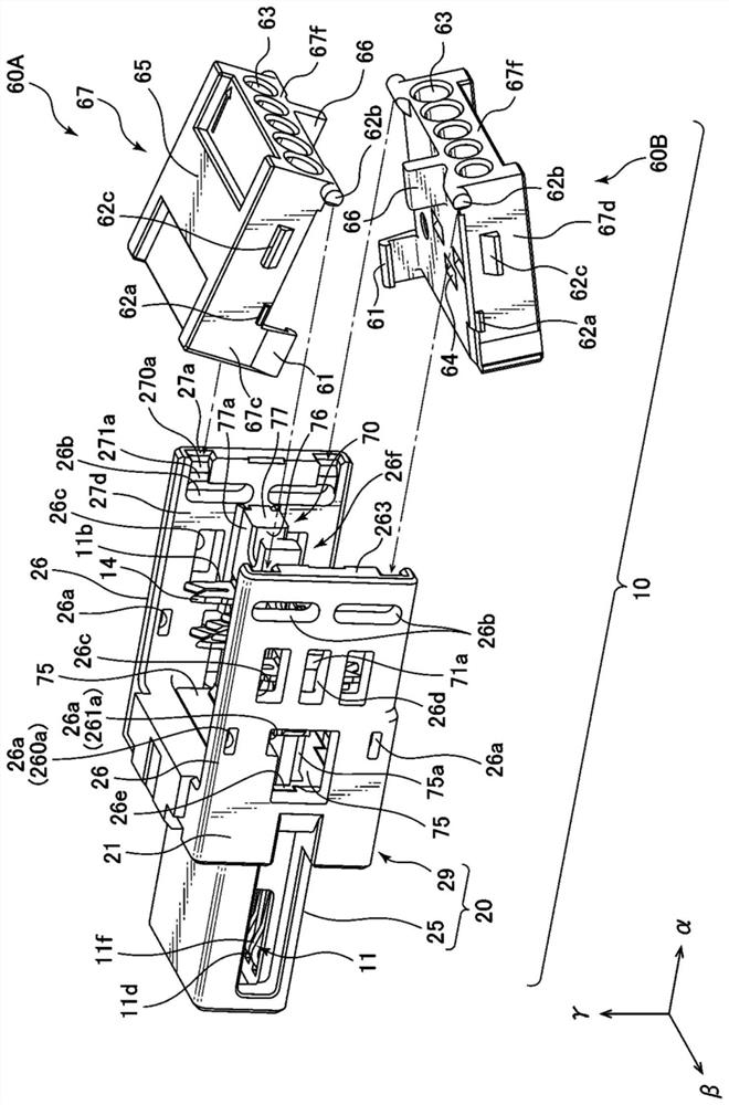
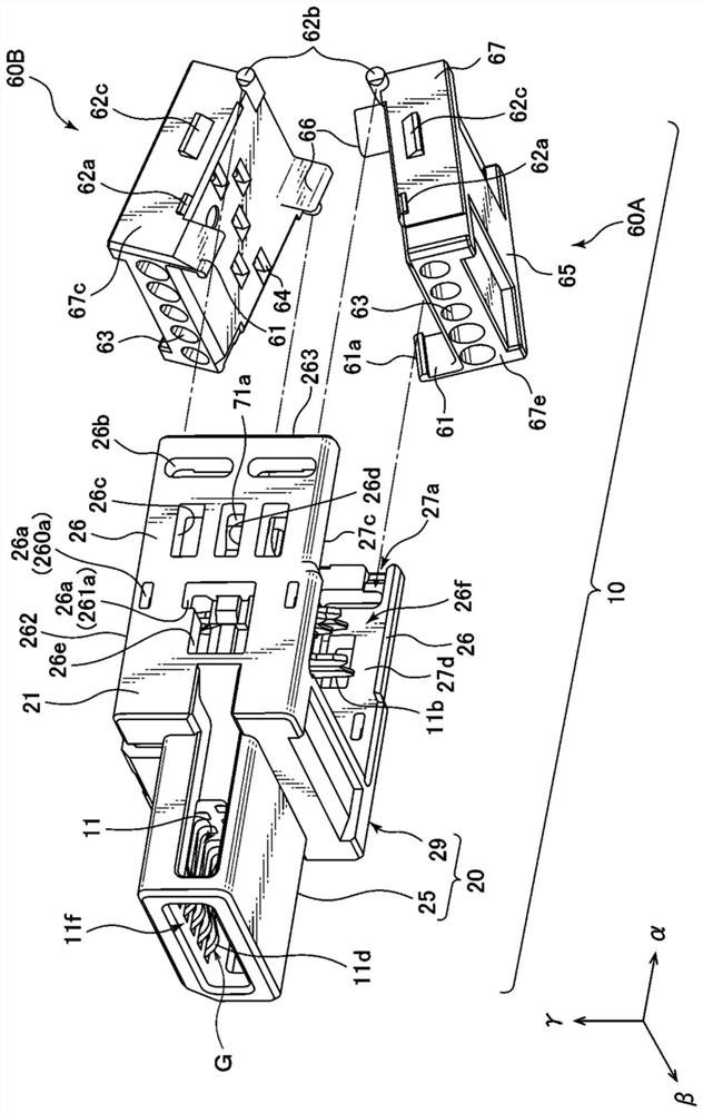
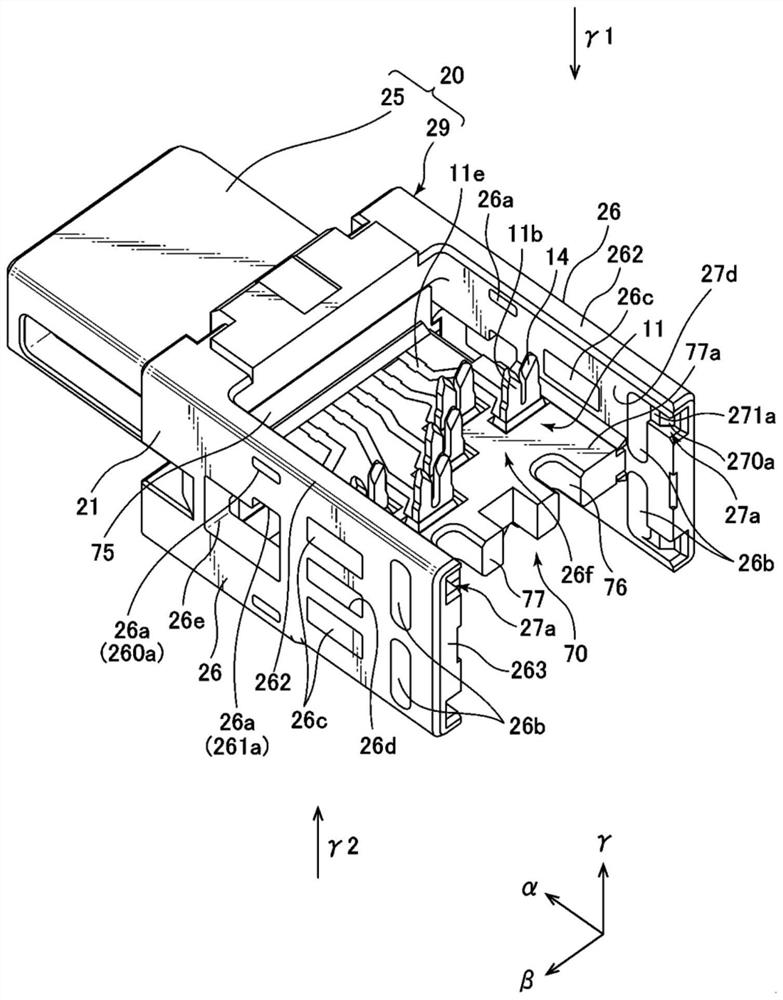
[0018] However, in the temporary fixing position, since the locking protrusion 62 of the cable holder 60 has not yet locked with the locking hole 26a on the side of the housing 20, only the locking protrusion 61a provided on the cable holder 60 and the locking hole 26a are locked. The tapered portion of the protrusion 62 collides with the locking protrusion 75a provided on the upright portion 75 of the terminal support 70 as part of the case 20 side and the upper edge 26d of the plate-shaped side wall 26, so the The state may not be called a stable state, so there are some problems in the convenience of use
[0019] In addition, after one end of the cable 5 is held by the cable holder 60, the process of setting the cable holder 60 as it is at the temporary fixing position of the housing 20 is somewhat cumbersome, for example, due to the The cable 5 protruding from the cable holder 60 at the temporarily fixed position exerts a force on the cable holder 60, so there is a problem that the cable holder 60 is easy to fall off from the temporarily fixed position of the housing 20. to advance further

Method used


Image

  • Cable connector including cable holder, and method of manufacturing cable connector
  • Cable connector including cable holder, and method of manufacturing cable connector
  • Cable connector including cable holder, and method of manufacturing cable connector

Examples


Embodiment Construction

[0052] Hereinafter, a cable connector according to a preferred embodiment of the present invention and an electrical connector device including the cable connector will be described with reference to the drawings. Here, although only the preferred embodiment of this invention was shown, it goes without saying that this embodiment does not limit this invention. For example, in this embodiment, a twisted-pair cable is used, but as will be clear from the following description, it is not limited to a twisted-pair cable, and cables such as a single cable and twisted-wire cable can also be used, for example.

[0053] The present invention is Figure 21 The structures of the components in the conventional cable connector 10 shown in fig. Hereinafter, the structure of these components will be described. Items that are not particularly described are considered to be the same as those in Patent Document 1, but it is of course not intended to be limited to the structure disclosed in Pa...


PUM


Abstract

The invention provides a cable connector and the like which can improve use convenience of a user and simplify operation. The cable connector comprises a housing and a cable holding body. The cable holding body is provided with at least three clamping parts on the outer side surface, and in the direction along the leading-out direction of leading out the cable from the cable holding body, the first clamping part is arranged on the side far away from the cable leading-out side, the second clamping part is arranged on the side close to the cable leading-out side, and the third clamping part is arranged between the first clamping part and the second clamping part. The inner side face of the housing is provided with corresponding clamping parts. The cable holding body is at least arranged at a first clamping position relative to the housing, wherein the first clamping part and the second clamping part are respectively clamped with the first corresponding clamping part and the second corresponding clamping part, but the third clamping part is not clamped with the third corresponding clamping part; and at the second clamping position, the first clamping part to the third clamping part are all clamped with the first corresponding clamping part to the third corresponding clamping part.

Description

technical field [0001] The present invention relates to a cable connector including a cable holder and a method for manufacturing the cable connector. Background technique [0002] International Publication No. 2018 / 016389 (Patent Document 1) shows an example of a conventional electrical connector device including a cable connector. Figure 21 to Figure 25 A part of the drawings disclosed in Patent Document 1 is shown. [0003] exist Figure 21 In , a perspective view of a conventional cable connector including a cable holder and an electrical connector device including the cable connector is shown together with a cable and a substrate. The electrical connector device 1 is constituted by a set of a cable connector 10 and an object connector 90 . [0004] The cable connector 10 can be fitted and removed from the board connector 90 along the arrow “α” direction in the figure. When the cable connector 10 is fitted to the board connector 90, the thin fitted portion 50a provid...

Claims


Application Information

Patent Timeline
Patent Type & Authority Applications(China)
IPC IPC(8): H01R13/72H01R11/11H01R13/40H01R13/516
CPCH01R13/72H01R11/11H01R13/40H01R13/516H01R4/2433H01R13/405H01R13/506H01R43/18H01R13/502
Inventor 迫田有祐
Owner HIROSE ELECTRIC GROUP
Learn More