Electronic lock

An electronic lock and deadbolt technology, applied in the field of electronic locks, can solve the problems of high production cost, poor safety, and simple structure, and achieve the effects of low production cost, stable performance, and simple structure

Inactive Publication Date: 2021-10-01
南京多泰智能科技有限公司
View PDF6 Cites 0 Cited by
  • Summary
  • Abstract
  • Description
  • Claims
  • Application Information

AI Technical Summary

Problems solved by technology

Under normal circumstances, the user of the cabinet inputs the correct electrical signal through an external device, so that the control circuit in the cabinet provides power to the lock mechanism. After the lock receives power, it realizes electronic opening. The structure is complex, the production cost is high, or the structure is simple and the safety is poor. In addition, due to the failure of the mechanical structure of the lock or the control circuit, the metal cabinet cannot be opened normally.

Method used


Image

  • Electronic lock
  • Electronic lock
  • Electronic lock

Examples


Embodiment

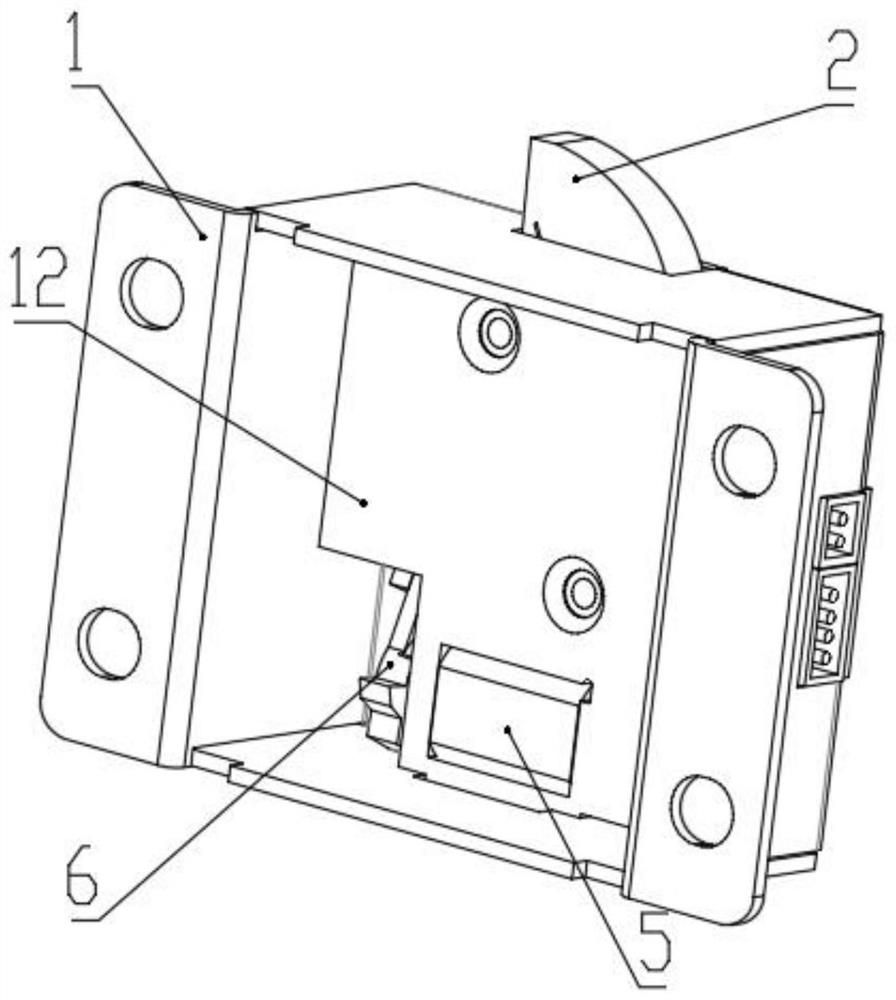
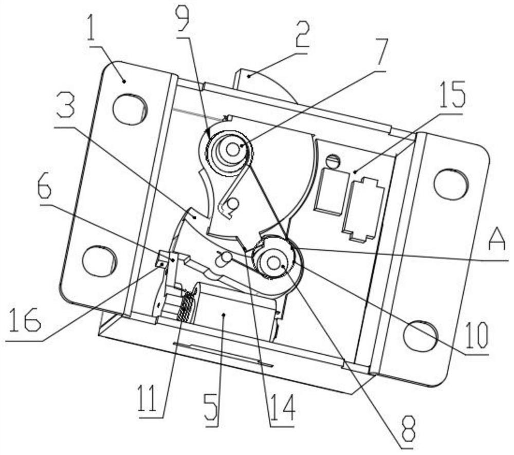
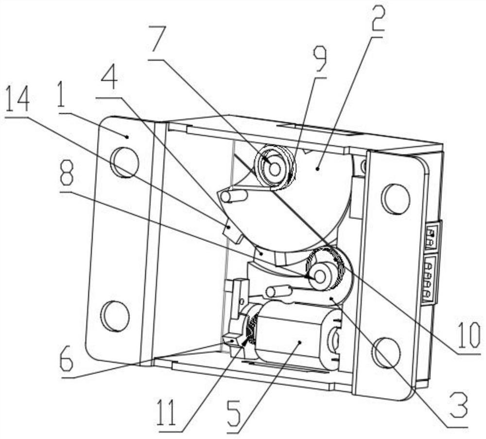
[0022] like Figure 1-4 As shown, an electronic lock includes a housing 1, a first shaft 7, a second shaft 8, a first torsion spring 9, a second torsion spring 10, a third torsion spring 11, wherein a lock 2, a lock tongue One end of 2 projects from the upper opening end of the housing 1, and the other end is in the housing 1, and the housing 1 is also provided with a locking block 3, the locking block 3 is movable with the lock tongue 2.

[0023] like figure 1 As shown, the appearance structure of the electronic lock lock is shown in the figure, there is a housing 1 in the figure, and there is a locking tongue 2 in the casing 1, and one end of the lock tongue 2 extends from the opening end of the housing 1. There is a motor 5, and there is a stop block 6 on the motor 5 shaft. Under the action of the third torsion spring 11, the side surface of the housing is opened, and the control circuit 15 in the housing passes This opening is electrically connected to the signal input circuit,...


PUM


Abstract

The invention belongs to the technical field of electronic locks, and particularly relates to an electronic lock. The electronic lock comprises a shell, a first rotating shaft, a second rotating shaft, a first torsion spring, a second torsion spring and a third torsion spring, wherein a spring bolt is arranged in the electronic lock, one end of the spring bolt extends out of the upper opening end of the shell, the other end of the spring bolt is arranged in the shell, a locking block is further arranged in the shell, the locking block is movably connected with the spring bolt, a motor is further arranged in the shell, and opening and closing of the motor are controlled through rotation of a check block on a shaft of the motor. The electronic lock has the advantages of simple structure and low production cost.

Description

Technical field [0001] The present invention belongs to the field of electronic lock technology, in particular, to an electronic lock. Background technique [0002] At present, the electronic lock used by security equipment such as a well-known box cabinet, considers the use of different structural electron locks. Under normal circumstances, the cabinet uses the correct electrical signal through the external device, so that the control circuit in the box provides power to the lock mechanism, and the lock has power, and the actual situation is: the existing box lock is either Structural complex, high production cost, simple structure, poor security, in addition, due to the failure of the lock mechanical structure or control circuit, the metal cabinet cannot be opened normally. [0003] The present invention belongs to the field of electronic lock technology, in particular to an electronic lock, including a housing, a first spool, a second axis, a first torsion spring, a second tor...

Claims


Application Information

Patent Timeline
Patent Type & Authority Applications(China)
IPC IPC(8): E05B47/00E05B15/04E05B15/00E05B15/10E05B9/00
CPCE05B47/0012E05B15/04E05B15/00E05B15/10E05B9/00E05B2015/0448
Inventor 杜新军
Owner 南京多泰智能科技有限公司
Why Eureka
Try Eureka