Full-automatic hose sheath winding machine

A fully automatic, sheathing machine technology, applied in the field of machinery, can solve the problems such as the inability to match the traveling speed of the hose assembly around the sheath, the inability to adjust, and the obstruction of sheath winding.

Pending Publication Date: 2021-10-08
全加机械设备(上海)有限公司
View PDF0 Cites 0 Cited by
  • Summary
  • Abstract
  • Description
  • Claims
  • Application Information

AI Technical Summary

Problems solved by technology

[0002] Existing fully automatic hose wrapping machines usually only have a single power head, only one end of the hose assembly is clamped and rotated by the powered head, and the other end of the hose assembly can only be rotated passively, which is easy Causes the hose assembly itself to be "twisted" during rotation, preventing the sheath from being smoothly wound onto the hose
[0003] In the process of wrapping the sheath in the existing automatic hose wrapping machine, the operator has to observe the sheath wrapping on the hose all the time because the rotation speed of the hose assembly and the traveling speed of the wrapping sheath cannot be matched synchronously. tightness, and manual intervention when problems are found
[0004] The locking device in the existing automatic hose wrapping machine can only clamp and fix the rubber hose assembly of a fixed size because the locking hole is fixed and cannot be adjusted, and it cannot realize multiple sizes at the same time. The clamping of the rubber hose assembly has a narrow application area; when it is necessary to clamp rubber hose assemblies of different sizes, it is necessary to replace another automatic hose wrapping machine of the corresponding size, which is complicated to operate and requires a high degree of manual participation. ,higher cost

Method used


Image

  • Full-automatic hose sheath winding machine
  • Full-automatic hose sheath winding machine
  • Full-automatic hose sheath winding machine

Examples


Embodiment 1

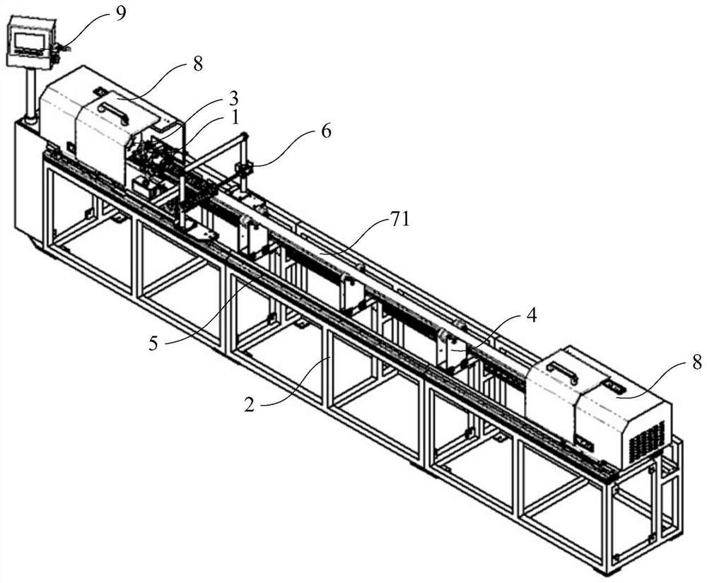
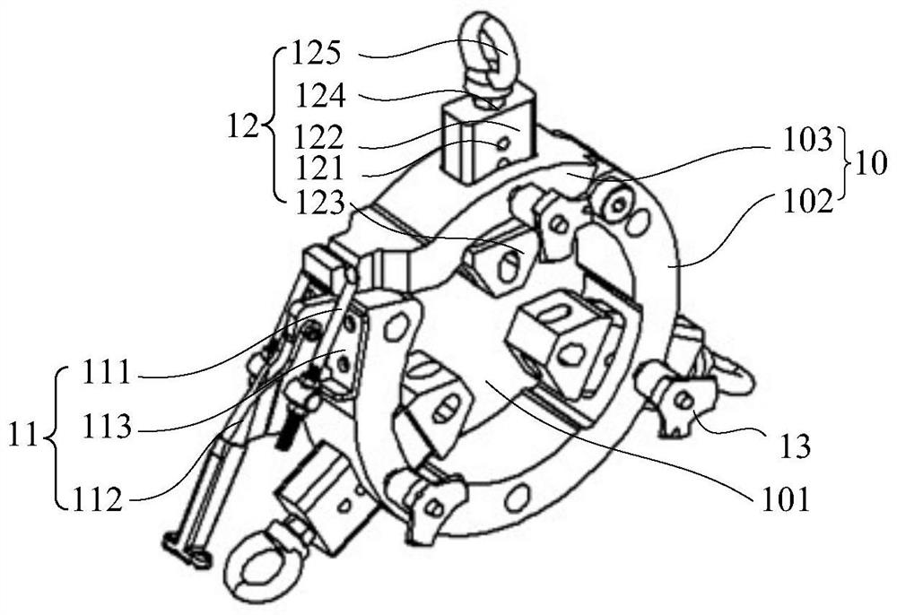
[0055] see figure 1 and figure 2 , a fully automatic hose wrapping machine is provided in this embodiment. The fully automatic hose wrapping machine includes: a frame 2, and the frame 2 is provided with guide rails 5 arranged in parallel at intervals. The guide rails 5 extend along the length direction of the frame 2; the control end machine head 3, the control end machine head 3 is located on the frame 2, is located between the guide rails 5, and is connected to the guide rails 5 , can slide along the guide rails 5; the free end head (not shown), the free end head is located on the frame 2, between the guide rails 5, connected with the guide rails 5, can Sliding along the guide rail 5, and the free end machine head has a distance from the control end machine head 3; the pneumatic tensioning device 91, the pneumatic tensioning device 91 is located at the bottom of the control end machine head 3, and the The control end machine head 3 is connected; the locking device 1, the ...

Embodiment 2

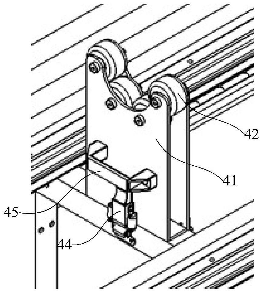
[0072] Please combine figure 1 and figure 2 refer to image 3 and Figure 4 , this embodiment also provides a fully automatic hose wrapping machine, the structure of the fully automatic hose wrapping machine described in this embodiment and the fully automatic hose wrapping machine described in Embodiment 1 Roughly the same, the difference between the two is: compared with the fully automatic hose wrapping machine in the first embodiment, the fully automatic hose wrapping machine described in this embodiment also includes a roller device 4, so The idler device 4 is located between the locking devices 1 for supporting the rubber hose assembly 71; the idler device 4 includes: a bracket 41, the bottom of which is fixed to the On the frame 2; the roller 42, the roller 42 is fixed on the top of the bracket 41; the hinge 43, the hinge 43 is located at the bottom of one side of the bracket 41, to connect the bracket 41 with the The frame 2 is hinged; the lock 44 is located at th...

Embodiment 3

[0078] Please combine Figure 1 to Figure 4 refer to Figure 6 , this embodiment also provides a fully automatic hose wrapping machine. The structure of the casing machine is roughly the same. The difference between the fully automatic hose wrapping machine in this embodiment and the above two embodiments is that in the fully automatic hose wrapping machine described in this embodiment, The guide rail 5 is located on the outside of the control end head 3 and the free end head, and extends along the length direction of the frame 2; the fully automatic hose wrapping machine also includes a second servo motor (not shown) and a second speed reducer (not shown), the second speed reducer is connected with the second servo motor; the fully automatic hose winding sheath machine also includes a sheath stroker 6, Such as Figure 6 As shown, the sheath stroker 6 includes: a stroke slide 61, the stroke slide 61 is arranged on the guide rail 5, connected with the second speed reducer, a...


PUM


Abstract

The invention provides a full-automatic hose sheath winding machine. The full-automatic hose sheath winding machine comprises a rack, a control end machine head, a free end machine head, a pneumatic straightening device, locking devices, a first servo motor and a first gear motor, wherein guide rails are arranged on the rack in parallel at intervals; the control end machine head is located on the rack; the free end machine head is located on the rack, and a distance is reserved between the free end machine head and the control end machine head; the pneumatic straightening device is located at the bottom of the control end machine head and connected with the control end machine head; the locking devices are located on the control end machine head and the free end machine head; and the first servo motor and the first gear motor are located in the control end machine head and the free end machine head. According to the full-automatic hose sheath winding machine, the locking devices are arranged on the control end machine head and the free end machine head, the two ends of a hose assembly can be clamped at the same time to rotate, and the situation that the hose assembly is twisted in the rotating process is effectively avoided.

Description

technical field [0001] The invention relates to the mechanical field, in particular to an automatic hose wrapping machine. Background technique [0002] Existing fully automatic hose wrapping machines usually only have a single power head, only one end of the hose assembly is clamped and rotated by the powered head, and the other end of the hose assembly can only be rotated passively, which is easy As a result, the hose assembly itself is "twisted" during rotation, which prevents the sheath from being smoothly wound onto the hose. [0003] In the process of wrapping the sheath in the existing automatic hose wrapping machine, the operator has to observe the sheath wrapping on the hose all the time because the rotation speed of the hose assembly and the traveling speed of the wrapping sheath cannot be matched synchronously. The degree of tightness, and manual intervention when problems are found. [0004] The locking device in the existing automatic hose wrapping machine can...

Claims


Application Information

Patent Timeline
Patent Type & Authority Applications(China)
IPC IPC(8): B29C63/06
CPCB29C63/06B29C63/0004
Inventor 吕峥朱振华卢一铃程鑫
Owner 全加机械设备(上海)有限公司
Why Eureka
Try Eureka