
Hand saw

A technology of hand saws and saw blades, which is applied in pad saws, saw blades, cross-cut saws, etc., which can solve the problems of enlarged saw teeth, easy hooking of saws, and increased distance between saw blades, so as to achieve smooth sawing start and smooth sawing Good effect in operation and cutting operation

Active Publication Date: 2021-10-08
UM INDS
View PDF6 Cites 0 Cited by
  • Summary
  • Abstract
  • Description
  • Claims
  • Application Information

AI Technical Summary

Problems solved by technology

However, on the other hand, since the pitch of the saw blades becomes larger at the front end side of the span portion of the saw blade, the pitch of the saw teeth becomes correspondingly larger, and there is a problem that the saw is likely to be caught on the object to be cut.

Method used


Image

  • Hand saw
  • Hand saw
  • Hand saw

Examples


Embodiment Construction

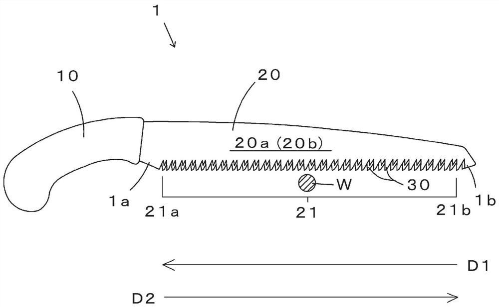
[0050] A hand saw according to an embodiment of the present invention will be described below with reference to the drawings.

[0051] First, refer to figure 1 , The hand saw 1 as one of the embodiments of the present invention is equipped with a handle portion 10 and a saw body 20 . A plurality of saw teeth 30 are provided on the blade span portion 21 of the saw body 20 .

[0052] However, the hand saw 1 shown in the figure is not shown as a folding saw, but it can also be a folding saw. In addition, the hand saw 1 shown in the figure is a single-edged saw with a saw blade span portion 21 equipped with saw teeth 30 only on one side of the saw body 20, but it is not limited thereto, and may also be provided on the saw body 20. A double-edged saw with blade spans 21 on both sides.

[0053] The hand saw 1 according to the embodiment of the present invention includes a pull saw and a push saw as a single-handed saw and a saw configured as a pull saw.

[0054] The pull saw is ...


PUM


Abstract

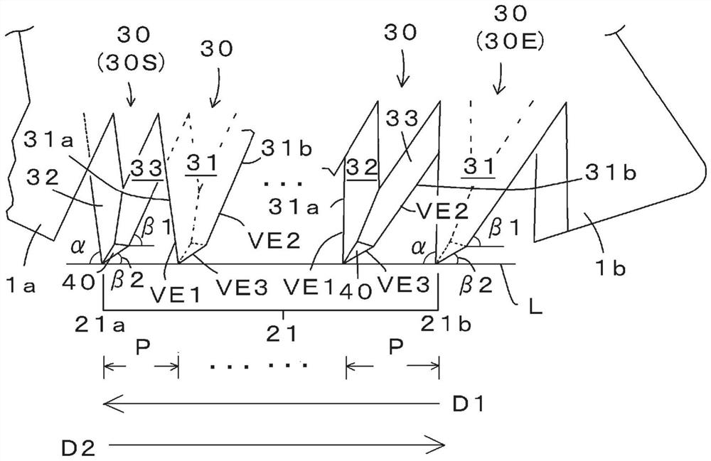
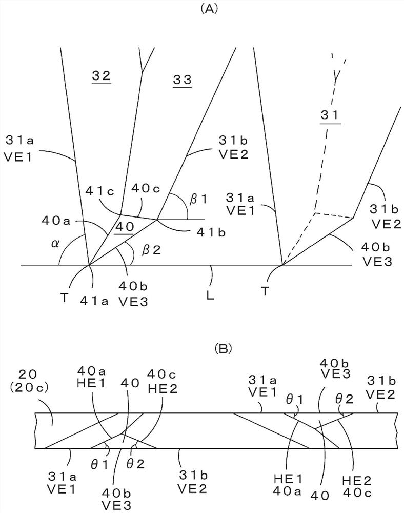
The present invention addresses the problem of providing a sharp hand saw that can ensure a smooth cutting operation and sufficiently apply the cutting pressure of a saw blade on an object to be cut at any location from the near side of a blade length part to the tip. A hand saw in which a front vertical edge VE1 and a rear vertical edge VE2 are provided to one vertical edged surface 31 of saw teeth 30 rising in a manner alternately flush with a front-side surface and a back-side surface of a saw body, a tip inclined cutting surface 40 being provided to the tip of each saw tooth 30. The angle of incidence [alpha] of the front vertical edge VE1 of each saw tooth 30 with respect to an edge line L of the saw is configured to gradually increase from an outward leading end side 21a to an outward trailing end side 21b of a blade length part 21.

Description

technical field [0001] This invention relates to hand saws. Background technique [0002] Most of the general hand saws in the past have saw teeth arranged at equal intervals. [0003] For example, in the case of cutting an object such as wood with a pull-saw at equal intervals, the cutting pressing force on the object may be weakened at the front end side of the blade span portion compared with the root side of the blade span portion. tendency. [0004] Therefore, there are provided various saws called jig saws in which the span portion of the saw blade is curved. By bending the saw body at the front end side of the blade span portion, the pressing force applied to the workpiece can be kept from decreasing even at the front end side. [0005] However, in the case of a jigsaw, there is a problem that the jigsaw cannot be applied to a type of saw in which it is not desirable to bend the blade span portion of the sawtooth. [0006] Therefore, there is also provided a hand ...

Claims


Application Information

Patent Timeline
Patent Type & Authority Applications(China)
IPC IPC(8): B27B33/10B27B21/00
CPCB23D61/121B27B33/10B27B21/04B23D61/12B23D49/14
Inventor 宫胁昌三
Owner UM INDS
Learn More