Current driving device

A current-driven, current technology, applied in electrical components, instruments, static indicators, etc., can solve the problems of inability to dynamically adjust, cannot be adjusted individually, and achieve the effect of improving brightness resolution

Pending Publication Date: 2021-10-12
MACROBLOCK INC
View PDF0 Cites 2 Cited by
  • Summary
  • Abstract
  • Description
  • Claims
  • Application Information

AI Technical Summary

Problems solved by technology

[0005] 3. If you need to increase the brightness resolution, you must also increase the circuit clock frequency
[0006] 4. The current value of the supply current must be consistent, and cannot be adjusted individually, nor can it be dynamically adjusted according to the frequency inside the circuit

Method used


Image

  • Current driving device
  • Current driving device
  • Current driving device

Examples


no. 1 example

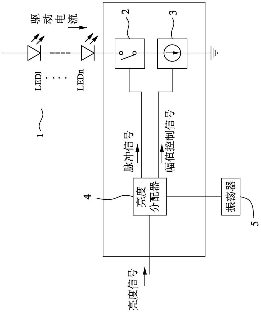
[0031] refer to figure 1 , the first embodiment of the current driving device of the present invention is suitable for driving a light-emitting component 1 according to a brightness value, and the current driving device includes a switch 2, a current generator 3, and a brightness distributor 4, which must be explained first Notably, in this embodiment, the light-emitting component 1 is specifically a single light-emitting diode, or a plurality of arrays of light-emitting diodes electrically connected to each other, and the light-emitting diode array can be any combination of RGBW or a single color.

[0032] The switch 2 is electrically connected to the light-emitting component 1, it receives a pulse signal and switches between conduction and non-conduction according to the pulse signal, and the switch 2 conducts in each pulse of the pulse signal , and not conducting outside each pulse of the pulse signal.

[0033] The current generator 3 is electrically connected to the switc...

no. 2 example

[0049] refer to Figure 8 , is the second embodiment of the current driving device of the present invention, said second embodiment is another implementation style derived from said first embodiment, specifically, includes a plurality of light emitting diodes electrically connected to each other The current driving device of the component 1, and the brightness distributor 4 of each current driving device generates a corresponding driving current to the respective electrically connected light-emitting components 1 according to the brightness value, so that multiple different light-emitting components 1 can be controlled simultaneously of luminous brightness.

[0050] In summary, the current drive device of the present invention can summarize the following advantages:

[0051] 1. The required pulse signal and amplitude control signal can be generated only according to the received luminance value, and there is no need to know the corresponding amplitude and pulse width related ...


PUM


Abstract

A current driving device is adapted to drive a light emitting element based on a brightness value and includes a switch, a current generator and a brightness divider. The switch switches between conduction and non-conduction based on a pulse signal. The current generator generates a drive current based on a magnitude control signal and the current flows through the light emitting element during conduction of the switch. The brightness divider generates the pulse signal and the magnitude control signal based on the brightness value. The average magnitude of the driving current during a period of the pulse signal is related to the brightness value, the brightness divider can generate the pulse signal and the magnitude control signal according to the brightness value, and the average magnitude of the driving current at present is related to the brightness value. Under the condition that the frequency is not increased, the brightness resolution ratio can be increased.

Description

technical field [0001] The invention relates to a power supply device, in particular to a current driving device suitable for light-emitting diodes. Background technique [0002] In the existing circuit structure used to control the light-emitting diode array of the display, each light-emitting unit is driven by a fixed current source connected in series with a switch, wherein the switch receives a pulse width modulation (PWM: Pulse Width Modulation) signal to generate Turning on and off makes the LED turn on and off, and the human eye can see a certain brightness value equivalently due to the persistence of vision. However, if higher brightness resolution or so-called high dynamic range (HDR: High Dynamic Range) imaging is required, it is often necessary to increase the operating frequency of the PWM signal to achieve it. Another architecture is to design the current source to receive pulses of different amplitudes. Wave to generate the corresponding current, the structure...

Claims


Application Information

Patent Timeline
Patent Type & Authority Applications(China)
IPC IPC(8): G09G3/32
CPCG09G3/32G09G2320/0626H05B45/325H05B45/10H05B45/46H05B45/32
Inventor 江定达翁文格
Owner MACROBLOCK INC
Why Eureka
Try Eureka