Speed limit identification and control method

A control method and speed limit technology, applied in speed/acceleration control, control device, non-electric variable control, etc., can solve the problem of inability to judge the speed limit requirements of the road ahead of the vehicle, insufficient comfort and safety, and reduce the probability of misidentification, etc. problems, to achieve the effect of reducing the probability of false recognition, improving comfort and safety, and ensuring functional convenience

Active Publication Date: 2021-10-19
DONGFENG MOTOR GRP
View PDF8 Cites 1 Cited by
  • Summary
  • Abstract
  • Description
  • Claims
  • Application Information

AI Technical Summary

Problems solved by technology

There are mainly the following problems: 1. The accuracy is not enough
2. Insufficient comfort and safety
The defect of this technical solution is: it is impossible to judge the speed limit requirement of the road ahead of the vehicle, which reduces the probability of misidentification; and through the driver's intervention and judgment, the driver's priority strategy is implemented, and the function is timely and automatic, ensuring the convenience of the function
The defects of this technical solution are: it is impossible to judge the speed limit requirement of the road ahead of the vehicle, which reduces the probability of misidentification; and through the driver's intervention and judgment, the driver's priority strategy is implemented, and the function is timely and automatic, ensuring the convenience of the function

Method used


Image

  • Speed limit identification and control method
  • Speed limit identification and control method
  • Speed limit identification and control method

Examples


Embodiment Construction

[0020] The technical solution (including the preferred technical solution) of the present invention will be further described in detail below by means of the accompanying drawings and listing some optional embodiments of the present invention. Apparently, the described embodiments are only some of the embodiments of the present invention, not all of them. Based on the embodiments of the present invention, all other embodiments obtained by persons of ordinary skill in the art without creative efforts fall within the protection scope of the present invention.

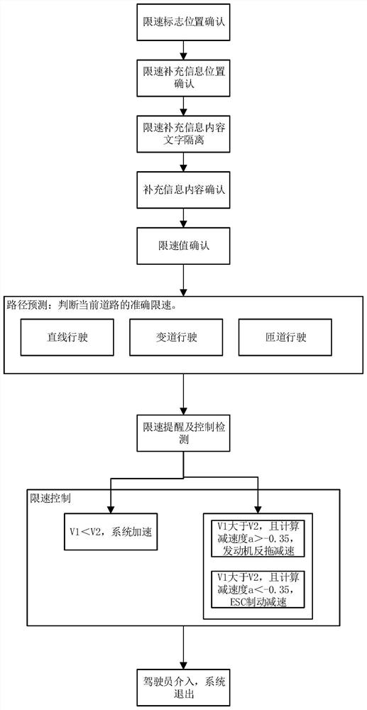
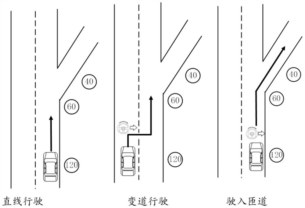
[0021] Preferably, the theoretical speed limit value on the current road segment is judged based on the speed limit value on the road speed limit plate on the current road segment and the speed limit supplementary information; the driver's desired path on the current road segment is judged based on the turn signal status and the steering wheel angle of the vehicle Trajectory; Based on the judgment of the driver's expected...


PUM


Abstract

The invention discloses a speed limit identification and control method. The method comprises the following steps: judging a theoretical speed limit value on a current road section based on a speed limit value on a road speed limit board on the current road section and speed limit supplementary information; judging a path track expected by a driver on the current road section based on the steering lamp state and the steering wheel angle of the vehicle; obtaining an execution speed limit value on the current road section based on the expected path track judgment of the driver on the current road section and the theoretical speed limit value on the current road section; and controlling the vehicle to accelerate or decelerate based on the execution speed limit value on the current road section and the actual vehicle speed on the current road section. By means of the vehicle-mounted camera, the vehicle speed is controlled by detecting the surrounding environment of the vehicle, sending the speed limiting information in real time and transmitting the speed limiting information to the vehicle speed control system, and the vehicle reaches the maximum passing speed on the premise that the vehicle does not violate the traffic safety laws and regulations.

Description

technical field [0001] The invention belongs to the technical field of vehicle control, and specifically discloses a speed limit identification and control method. Background technique [0002] The speed control mainly depends on the driver's active manipulation after recognizing the road speed limit sign. When the driver has inattention, fatigue driving or human eyes mistakenly recognizes or misses to recognize the road speed limit sign, it is very easy to overspeed and even cause traffic safety accidents. In order to solve the above-mentioned technical problems, the prior art mainly uses navigation and cameras to identify the current speed limit value of the lane to remind the driver of the current speed requirement. There are mainly the following problems: 1. The accuracy is not enough. Speed ​​limit information should include the supplemental information content below. Because the supplementary information cannot be recognized, or through an unreasonable strategy (suc...

Claims


Application Information

Patent Timeline
IPC IPC(8): G06K9/00G06K9/34B60K31/00G05D1/02
CPCB60K31/00G05D1/0246
Inventor 陈松
Owner DONGFENG MOTOR GRP
Why Eureka
Try Eureka