Unmanned aerial vehicle takeoff assisting device

A power-assisted device and UAV technology, which is applied in the direction of launching/dragging transmission devices, etc., can solve the problems of unstable flight trajectory, hard collision damage of UAV devices, lack of UAV safety protection related structures, etc., and achieve economical carrying Space and cost saving effects

Inactive Publication Date: 2021-10-29
湖州泰益智能科技有限公司
View PDF1 Cites 0 Cited by
  • Summary
  • Abstract
  • Description
  • Claims
  • Application Information

AI Technical Summary

Problems solved by technology

[0003] The take-off process of the existing UAV is mainly for the operator to place the UAV on the ground, and then need to have a very strong control ability and proficiency to make the UAV take off smoothly. When encountering extremely bad weather, The UAV may not be able to take off normally, even after the UAV takes off, the flight path will be extremely unstable, so it is necessary to set up a simple booster device to help the UAV take off
[0004] And the patent No. is CN111645873B disclosed a kind of unmanned aerial vehicle take-off assisting device, comprises base plate, and described base plate top middle part is provided with hollow column, and described hollow column top is fixedly provided with round table, and described base plate top four corners is provided with support bar , the top of the support rod is provided with a square platform; the UAV take-off booster device lacks a safety protection related structure for the sudden power failure of the drone, and when the drone is ejected by the booster device to help take off, if The drone suddenly lost power and fell directly onto the device. The drone had a hard collision with the device and was seriously damaged.

Method used


Image

  • Unmanned aerial vehicle takeoff assisting device
  • Unmanned aerial vehicle takeoff assisting device
  • Unmanned aerial vehicle takeoff assisting device

Examples


Embodiment Construction

[0027] Next, the technical solutions in the embodiments of the present invention will be described in connection with the drawings of the embodiments of the present invention, and it is understood that the described embodiments are merely the embodiments of the present invention, not all of the embodiments.

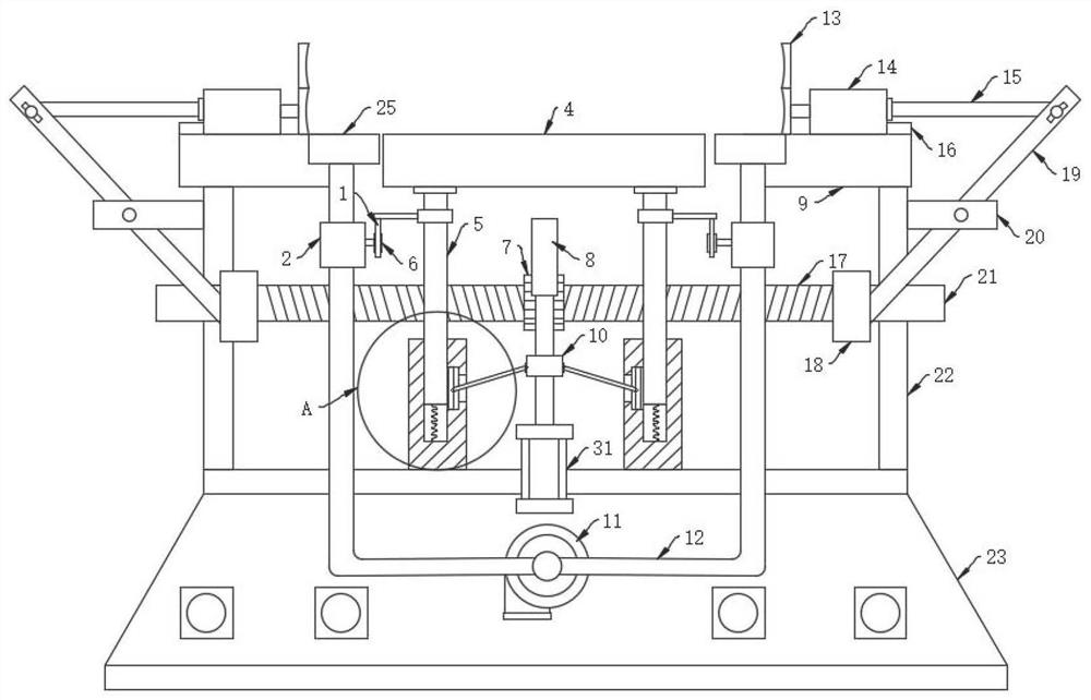
[0028] Refer Figure 1-5 , A drone starting assist force device, including a base 23, and the top of the base 23 is fixedly coupled to the bracket 22, and the top portion of the bracket 22 is fixedly coupled to the finite block 20, and the limit block 20 rotates to the reverse rod 19, The top of the reverse rod 19 is rotatably coupled to one end of the horizontal rod 15, and the top seat 9 is fixed to the top of the bracket 22. The top seat 9 is fixed in the horizontal direction to which the rail 16 is slidably connected in the horizontal direction. 14, slide The block 14 is fixedly connected to the splint 13.

[0029] The sliding block 14 is fixed to the end of the pinch 13, ...


PUM


Abstract

The invention discloses an unmanned aerial vehicle takeoff assisting device, and relates to the technical field of unmanned aerial vehicle takeoff assisting equipment. The unmanned aerial vehicle takeoff assisting device comprises a base, supports are fixedly connected to the two sides of the top of the base, a top seat is fixedly connected to the tops of the supports, a guide rail is fixedly connected to the upper surface of the top seat in the horizontal direction, a sliding block is slidably connected to the guide rail in the horizontal direction, and one end of the sliding block is fixedly connected with a clamping plate. A sliding block is slidably connected to the top of a top seat in the horizontal direction, a clamping plate is fixedly connected to one end of the sliding block, a two-way screw rotationally connected to the middle of a support locks the two-way screw under the cooperation of a middle toothed bar fixedly connected to the output end of an air cylinder and a middle gear, the two-way screw drives a reversing rod to rotate along a limiting block through a driven nut, and the limiting block drives the clamping plate to clamp the unmanned aerial vehicle at the top of the objective table, so that an unmanned aerial vehicle storage device does not need to be additionally arranged, the unmanned aerial vehicle can be directly stored on the takeoff assisting device, and the carrying space and cost of the unmanned aerial vehicle are saved.

Description

Technical field [0001] The present invention relates to the technical field of drone to help fly, and more particularly to a drone starting assistance device. Background technique [0002] Unmanned aircraft is referred to as "drone", which is a non-supported aircraft that uses radio remote control equipment and the self-propelled program control. There is no cockpit on the machine, but equipment such as an automatic driver, program control device is installed. Grounds, ships, or engine remote control stations conduct track, position, remote, telemetry, and digital transmission through radar. You can take off as a normal aircraft as a normal aircraft or to launch the rocket to be launched by the mother machine. [0003] The existing drone take-away process is mainly placed on the ground to the ground, and then requires very strong handling capabilities and proficiency to make the drone launched smoothly, when encountering extremely bad weather, The drone may not take normally, eve...

Claims


Application Information

Patent Timeline
Patent Type & Authority Applications(China)
IPC IPC(8): B64F1/06
CPCB64F1/06
Inventor 沈明明
Owner 湖州泰益智能科技有限公司
Why Eureka
Try Eureka