Chip packaging structure, chip packaging method, and optical computing device

A chip packaging structure and photonic chip technology, which is applied in optical computing equipment, circuit optical components, printed circuit assembly of electrical components, etc., can solve the problems of photonic chip deformation and low optical coupling efficiency, and achieve good optical coupling efficiency. Effect

Active Publication Date: 2022-08-02
HANGZHOU GUANGZHIYUAN TECH CO LTD
View PDF3 Cites 0 Cited by
  • Summary
  • Abstract
  • Description
  • Claims
  • Application Information

AI Technical Summary

Problems solved by technology

[0004] The embodiment of the present application provides a chip packaging structure, a chip packaging method, and an optical computing device, which are used to solve the problem of the photonic chip caused by the pressing force of the chip socket on the photonic chip when the chip socket is used to install the photonic chip on the circuit board. The problem of inefficient optical coupling caused by deformation

Method used


Image

  • Chip packaging structure, chip packaging method, and optical computing device
  • Chip packaging structure, chip packaging method, and optical computing device
  • Chip packaging structure, chip packaging method, and optical computing device

Examples


Embodiment Construction

[0024] The technical solutions in the embodiments of the present application will be clearly described below with reference to the drawings in the embodiments of the present application. Obviously, the described embodiments are only a part of the embodiments of the present application, rather than all the embodiments. Based on the embodiments in this application, all other embodiments obtained by those of ordinary skill in the art without creative efforts shall fall within the protection scope of this application.

[0025] Unless otherwise defined, all technical and scientific terms used herein have the same meaning as commonly understood by one of ordinary skill in the technical field to which this application belongs. The terms used herein in the specification of the application are for the purpose of describing specific embodiments only, and are not intended to limit the application.

[0026] The "including" mentioned throughout the specification and claims is an open-ended...


PUM


Abstract

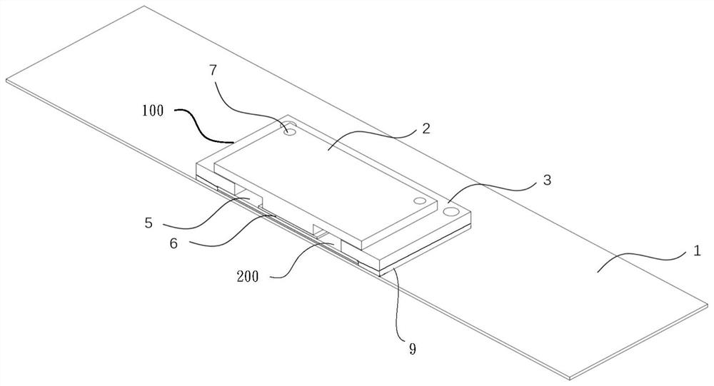
Embodiments of the present application provide a chip packaging structure, a chip packaging method, and an optical computing device. Wherein, the structure includes: a circuit board, a chip socket mounted on the circuit board, and a photonic chip mounted on the chip socket; the chip socket includes a plurality of elastic electrical connectors, a first pressing member and a second pressing member the first pressing part and the second pressing part are formed separately; the plurality of elastic electrical connecting parts are located between the circuit board and the photonic chip which are arranged oppositely, and the elastic electrical Both ends of the connector are in electrical contact with the circuit board and the photonic chip respectively; the first pressing member is pressed on the edge region of the photonic chip, and the second pressing member is pressed on the photonic chip the central area of ​​the chip, so that the elastic electrical connector is in a compressed state. The technical solutions provided in the embodiments of the present application can easily control and obtain favorable deformation conditions, so as to achieve better optical coupling efficiency.

Description

technical field [0001] The present application relates to the field of semiconductor technology, and in particular, to a chip packaging structure, a chip packaging method, and an optical computing device. Background technique [0002] Compared with traditional electronic chips, photonic chips realize data transmission and processing by manipulating optical signals, and photonic chips (or optical chips) have the advantages of high speed, low delay, and low power consumption. [0003] Typically, a photonic chip is packaged by a photonic bare chip and a light source (eg, a small laser) that provides the photonic bare chip with an optical signal. The coupling efficiency of the light emitted by the light source into the photonic die is a key factor limiting how much light can enter the interior of the photonic die. SUMMARY OF THE INVENTION [0004] The embodiments of the present application provide a chip packaging structure, a chip packaging method, and an optical computing d...

Claims


Application Information

Patent Timeline
Patent Type & Authority Patents(China)
IPC IPC(8): H05K1/02H05K1/18H05K3/32G06E3/00
CPCH05K1/0274H05K1/18H05K3/32G06E3/001
Inventor 薛志全孟怀宇沈亦晨
Owner HANGZHOU GUANGZHIYUAN TECH CO LTD
Why Eureka
Try Eureka