Hydrostatic thrust test platform for underwater propeller
A test platform and thruster technology, applied in the direction of force/torque/power measuring instruments, instruments, measuring devices, etc., can solve problems such as complex structure, error, and influence of test results
- Summary
- Abstract
- Description
- Claims
- Application Information
AI Technical Summary
Problems solved by technology
Method used
Image

Examples
Embodiment 1
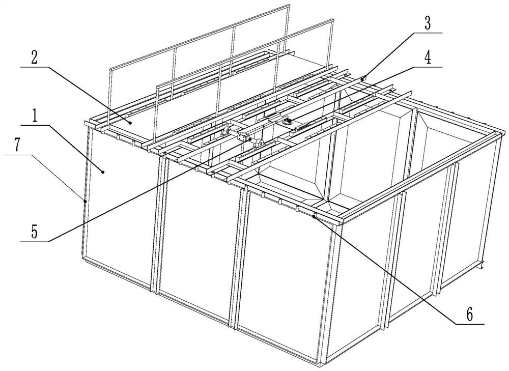
[0030] This embodiment proposes a hydrostatic thrust test platform for underwater propellers, such as figure 1 As shown, it includes a pool 1, a walking platform 2, a beam 3, a pressure gauge 4, and a thrust testing mechanism 5. Mainly, the horizontal force generated by the underwater propeller is converted into vertical downward pressure by the thrust testing mechanism 5, and then read by the pressure gauge 4, thereby realizing the measurement of the thrust value of the underwater propeller.
[0031] The periphery of the pool 1 is provided with a steel frame 7, and the top of the steel frame 7 is provided with a circle of C-shaped steel beams, and the C-shaped steel beam is provided with a mounting seat-6, and the mounting seat-6 in the present embodiment is designed Socket with mounting holes. The steel structure frame 7 can strengthen the strength of the pool 1, and can also bear the weight of the upper structure.
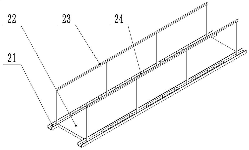
[0032] like figure 2 As shown, the walking platform 2 ...
Embodiment 2
[0042]The principle of this embodiment is similar to that of Embodiment 1, the difference is that the position adjustment of the walking platform 2, the span beam 3, the thrust test mechanism 5 and the length adjustment of the rotating force arm 53 and the pressure arm 56 in the embodiment are all done manually. Completed. In order to realize automatic adjustment, in the present embodiment, the mounting base 6 and the mounting base 2 24 are all set as slide rail seats, and the driving mechanism 1 and the driving mechanism 2 are provided at the same time, and the two ends of the walking platform 2 and the span beam 3 in the length direction Slidingly connected on the mounting seat 6, the driving mechanism 1 is used to drive the walking platform 2 and the cross beam 3 to slide on the mounting seat 6, and the bearing seat 51 and the pressure gauge mounting seat 54 are all slidably connected to the mounting seat On the second 24, the second driving mechanism is used to drive the b...
PUM
 Abstract
Description
Claims
Application Information
 - R&D Engineer
- R&D Manager
- IP Professional
- Industry Leading Data Capabilities
- Powerful AI technology
- Patent DNA Extraction
Browse by: Latest US Patents, China's latest patents, Technical Efficacy Thesaurus, Application Domain, Technology Topic.
© 2024 PatSnap. All rights reserved.Legal|Privacy policy|Modern Slavery Act Transparency Statement|Sitemap