A multi-purpose plate precision processing device
A precision machining and multi-purpose technology, applied in the direction of feeding devices, metal processing equipment, metal processing machinery parts, etc., can solve the problems of increased defective rate, poor drilling and grinding accuracy, waste of labor, etc., to prevent excessive extrusion force The effect of large breaking, drilling and grinding with precise positioning and avoiding potential safety hazards
- Summary
- Abstract
- Description
- Claims
- Application Information
AI Technical Summary
Problems solved by technology
Method used
Image
Examples
Embodiment 1
[0046] as attached figure 1 to attach Figure 20 Shown:
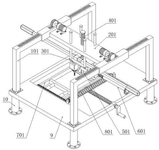
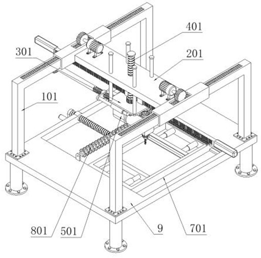
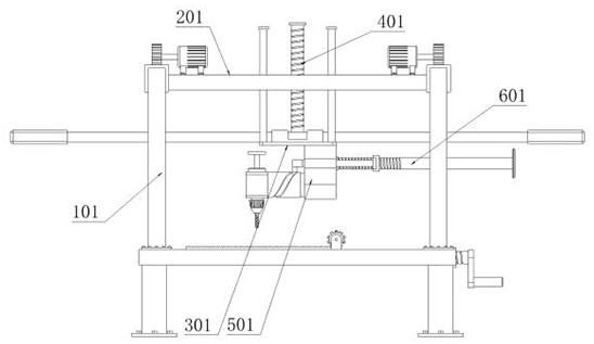
[0047] The present invention provides a multi-purpose plate precision processing device, which includes a support part 1; two sets of support parts 1 are provided, and the bottoms of the two sets of support parts 1 are fixedly connected with mounting plates 9; the four corners of the bottom of the mounting plate 9 are respectively fixedly connected with mounting legs 10. Two groups of supporting parts 1 are slidingly fitted with running device 2, and floating device 3 is slidably connected to running device 2; driving part 4 is threaded on running device 2; processing device 5 is fixedly connected to the bottom of floating device 3, and A propulsion part 6 is slidably connected to the processing device 5 ; a fixed part 7 is slidably connected to the mounting plate 9 , and the cleaning part 8 is connected to the rotating shaft of the mounting plate 9 .
[0048] as attached Image 6 to attach Figure 10 As shown, the ...
Embodiment 2
[0051] as attached Figure 14 to attach Figure 17 As shown, the fixed part 7 includes: a fixed frame 701, the two sides of the fixed frame 701 are slidably connected to the mounting plate 9; the cleaning rack 702 is fixedly connected to the side of the fixed frame 701; the screw rod 703 is installed, and the screw rod is installed 703 is threadedly connected on the mounting plate 9, and the front end rotation shaft of the mounting screw 703 is connected to the side of the fixed frame 701; the fixed part 7 also includes: fixed sleeves 704, four fixed sleeves 704 are provided, and four fixed sleeves 704 are respectively fixedly connected to both sides of the inner side of the fixed frame 701, and the four fixed sleeves 704 are equipped with springs inside; two fixed plates 705 are provided, and the two fixed plates 705 are fixedly connected to the four fixed sleeves 704 respectively. Above; the cleaning device 8 includes: a cleaning hair roller 801, which is connected to the m...
Embodiment 3
[0053] as attached Figure 20 As shown, on the basis of the second embodiment, the other structures remain unchanged. This embodiment provides another structural form of the fixing part 7, which solves the problem that after the two fixing plates 705 on the fixing part 7 are actually clamped with the mounting plate, Since the four fixing sleeves 704 can be telescopically moved, the plate is easy to shake left and right, thereby reducing the processing accuracy of the plate. The fixing part 7 includes: a fixing frame 701, and the two sides of the fixing frame 701 are slidably connected to the mounting plate 9; Clean up the rack 702, and the rack 702 is fixedly connected to the side of the fixed frame 701; the screw mandrel 703 is installed, and the screw mandrel 703 is threaded on the mounting plate 9, and the rotating shaft of the front end of the screw mandrel 703 is connected to the side of the fixed frame 701; Part 7 also includes: fixed sleeve 704, four fixed sleeves 704 a...
PUM
 Abstract
Description
Claims
Application Information
 - R&D
- Intellectual Property
- Life Sciences
- Materials
- Tech Scout
- Unparalleled Data Quality
- Higher Quality Content
- 60% Fewer Hallucinations
Browse by: Latest US Patents, China's latest patents, Technical Efficacy Thesaurus, Application Domain, Technology Topic, Popular Technical Reports.
© 2025 PatSnap. All rights reserved.Legal|Privacy policy|Modern Slavery Act Transparency Statement|Sitemap|About US| Contact US: help@patsnap.com


