
Multipurpose plate precision machining device

A precision machining and multi-purpose technology, applied in the direction of feeding devices, metal processing equipment, metal processing machinery parts, etc., can solve the problems of poor drilling and grinding accuracy, increased defective rate, waste of labor, etc., to achieve drilling and grinding positioning Precise, preventing excessive extrusion force from breaking, and avoiding safety hazards

Active Publication Date: 2021-11-12
JIANGSU TANG BASE BUILDING MATERIALS TECH GRP CO LTD
View PDF9 Cites 2 Cited by
  • Summary
  • Abstract
  • Description
  • Claims
  • Application Information

AI Technical Summary

Problems solved by technology

[0005] In order to solve the above technical problems, the present invention provides a multi-purpose plate precision processing device to solve the problem that the existing plate processing device is not equipped with a multi-axis moving combination, the drilling and grinding accuracy is poor, and there is no push-type drilling and grinding switching device. The production efficiency is low, labor is wasted, and the grinding angle cannot be adjusted at the same time. The grinding is not comprehensive enough, which affects the quality of plate processing and reduces customer satisfaction during sales. There is no processing and cleaning device, and the accumulation of iron filings will affect the drilling and grinding effect and is not convenient for work. The personnel check the status of the processed parts in real time, and there is no manually adjustable drive device, so the staff cannot adjust the grinding and drilling strength according to the different boards. While increasing the defective rate, the drill bit is very easy to break, posing a safety hazard.

Method used


Image

  • Multipurpose plate precision machining device
  • Multipurpose plate precision machining device
  • Multipurpose plate precision machining device

Examples


Embodiment 1

[0046] as attached figure 1 to attach Figure 20 Shown:

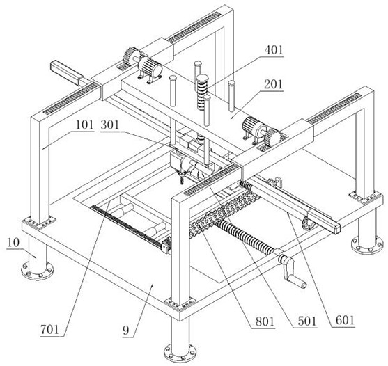
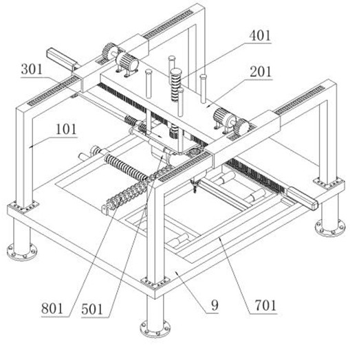
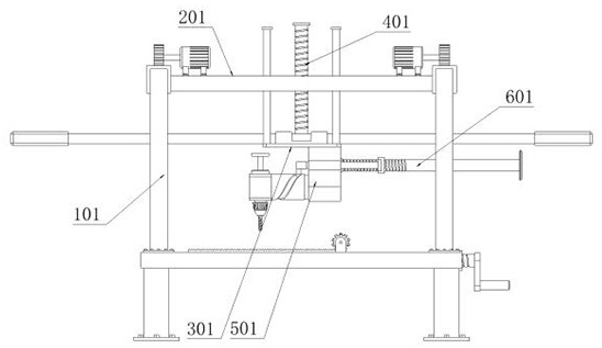
[0047] The present invention provides a multi-purpose plate precision processing device, which includes a support part 1; two sets of support parts 1 are provided, and the bottoms of the two sets of support parts 1 are fixedly connected with mounting plates 9; the four corners of the bottom of the mounting plate 9 are respectively fixedly connected with mounting legs 10. Two groups of supporting parts 1 are slidingly fitted with running device 2, and floating device 3 is slidably connected to running device 2; driving part 4 is threaded on running device 2; processing device 5 is fixedly connected to the bottom of floating device 3, and The processing device 5 is slidably connected with a propelling part 6 ; the fixed part 7 is slidably connected with the mounting plate 9 , and the rotating shaft of the mounting plate 9 is connected with a cleaning part 8 .

[0048] as attached Figure 6 to attach Figure 10 As show...

Embodiment 2

[0051] as attached Figure 14 to attach Figure 17 As shown, the fixed part 7 includes: a fixed frame 701, the two sides of the fixed frame 701 are slidably connected to the mounting plate 9; the cleaning rack 702 is fixedly connected to the side of the fixed frame 701; the screw rod 703 is installed, and the screw rod is installed 703 is threadedly connected on the mounting plate 9, and the front end rotation shaft of the mounting screw 703 is connected to the side of the fixed frame 701; the fixed part 7 also includes: fixed sleeves 704, four fixed sleeves 704 are provided, and four fixed sleeves 704 are respectively fixedly connected to both sides of the inner side of the fixed frame 701, and the four fixed sleeves 704 are equipped with springs inside; two fixed plates 705 are provided, and the two fixed plates 705 are fixedly connected to the four fixed sleeves 704 respectively. Above; the cleaning device 8 includes: a cleaning hair roller 801, which is connected to the m...

Embodiment 3

[0053] as attached Figure 20 As shown, on the basis of the second embodiment, the other structures remain unchanged. This embodiment provides another structural form of the fixing part 7, which solves the problem that after the two fixing plates 705 on the fixing part 7 are actually clamped with the mounting plate, Since the four fixing sleeves 704 can be telescopically moved, the plate is easy to shake left and right, thereby reducing the processing accuracy of the plate. The fixing part 7 includes: a fixing frame 701, and the two sides of the fixing frame 701 are slidably connected to the mounting plate 9; Clean up the rack 702, and the rack 702 is fixedly connected to the side of the fixed frame 701; the screw mandrel 703 is installed, and the screw mandrel 703 is threaded on the mounting plate 9, and the rotating shaft of the front end of the screw mandrel 703 is connected to the side of the fixed frame 701; Part 7 also includes: fixed sleeve 704, four fixed sleeves 704 a...


PUM


Abstract

The invention provides a multipurpose plate precision machining device. The multipurpose plate precision machining device comprises two sets of supporting parts. A mounting plate is fixedly connected with the bottoms of the two groups of supporting parts; mounting legs are fixedly connected to four corners of the bottom of the mounting plate; operation devices slidably sleeve the two groups of supporting parts, and the operation devices are slidably connected with floating devices; the operation devices are in threaded connection with a driving part; machining devices are fixedly connected to the bottoms of the floating devices, and pushing parts are slidably connected with the machining devices; and a fixing part is slidably connected to the mounting plate, a cleaning part is connected to the mounting plate in a rotating shaft mode, rotating switching of the machining sets can be achieved by adopting the mode that a machining shaft frame is rotationally connected with a rotating shaft, meanwhile, a threaded groove is formed in the rotating shaft, pushing of ball heads on the pushing parts is matched, different machining modes of the machining sets can be replaced more conveniently, and the production and machining efficiency is greatly improved.

Description

technical field [0001] The invention belongs to the technical field of mechanical processing, and more specifically relates to a multi-purpose plate precision processing device. Background technique [0002] Machining refers to the process of changing the shape or performance of a workpiece through a mechanical device. According to the difference in processing methods, it can be divided into cutting processing and pressure processing. In the actual machining process, drilling and grinding of plates are often used processing methods. At this time, a good precision plate Processing equipment is particularly important. [0003] For example, the application number: CN201711480481.0 relates to a plate processing device. It includes frame, bending part, cleaning part and oiling part. The bending part includes mould, fixed box and telescopic cylinder. There are grooves on the mold and limit plates on the mold. The fixed box is fixed on the frame. The upper and lower sides of the...

Claims


Application Information

Patent Timeline
Patent Type & Authority Applications(China)
IPC IPC(8): B24B7/10B24B41/02B24B41/06B23P23/04B23Q1/25B23Q5/40B23Q11/00
CPCB24B7/10B24B41/02B24B41/068B23P23/04B23Q1/25B23Q5/40B23Q11/0042
Inventor 李衍奎
Owner JIANGSU TANG BASE BUILDING MATERIALS TECH GRP CO LTD
Learn More