A centrifugal pendulum absorber
A centrifugal pendulum shock absorber, center axis technology, applied in the field of vehicles
- Summary
- Abstract
- Description
- Claims
- Application Information
AI Technical Summary
Problems solved by technology
Method used
Image

Examples
Embodiment Construction
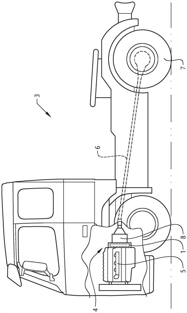
[0040] figure 1 A vehicle 3 in the form of a heavy truck is schematically shown according to an embodiment of the invention. The vehicle 3 comprises a powertrain 4 having an engine 5 connected to a crankshaft (not shown) to which a flywheel arrangement 1 is connected for common rotation. A drive shaft 6 connects the engine 5 to drive wheels 7 of the vehicle 3 via a transmission 8 which is connected to the flywheel via a clutch (not shown).
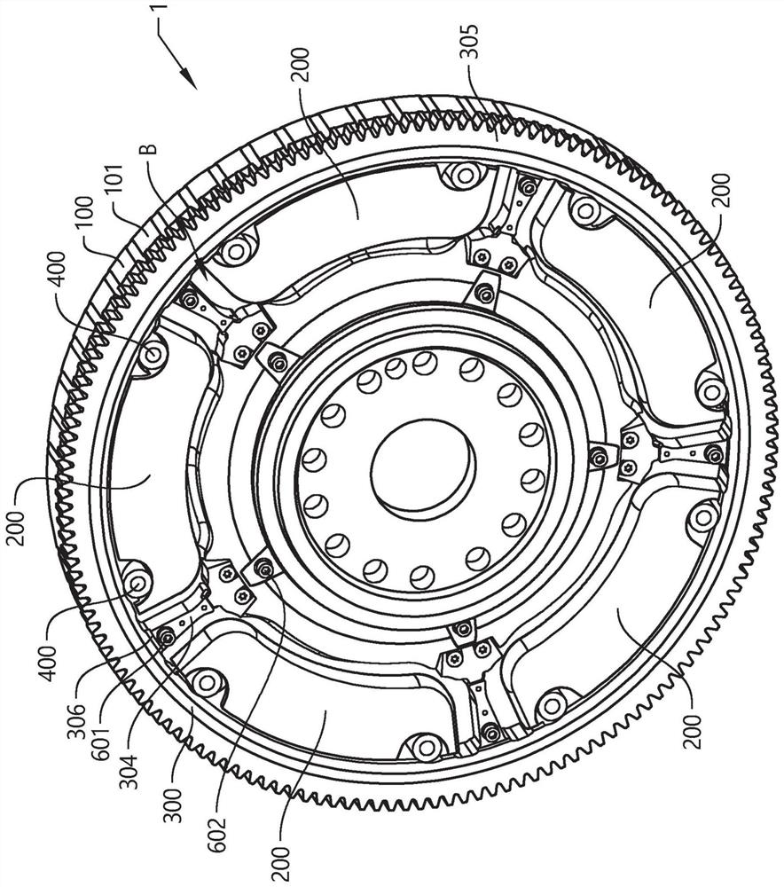
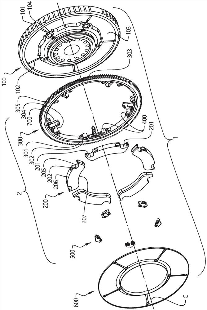
[0041] figure 2 A flywheel arrangement 1 according to an embodiment of the invention is shown in more detail in . Also refer to the flywheel arrangement 1 shown in exploded view image 3 and a part of the flywheel arrangement shown in more detail Figure 4 . The flywheel arrangement 1 comprises: a flywheel 100 configured to be connected to a crankshaft of an engine for common rotation about a central axis C; and a centrifugal pendulum damper 2 . The centrifugal pendulum shock absorber 2 includes a plurality of pendulum weights 200 a...
PUM
 Abstract
Description
Claims
Application Information