Eureka AIR delivers breakthrough ideas for toughest innovation challenges, trusted by R&D personnel around the world.

Spotlight antenna convenient for angle adjustment

A technology for adjusting the angle and the antenna, which is applied in the directions of the antenna, antenna support/installation device, electrical components, etc. It can solve the problems of inconvenience, low debugging and installation efficiency, etc., and achieve the effect of convenient adjustment, improved debugging and installation efficiency, and convenient use.

Active Publication Date: 2021-11-30
CHINA TELECOM CORP LTD
View PDF12 Cites 1 Cited by
  • Summary
  • Abstract
  • Description
  • Claims
  • Application Information

AI Technical Summary

Problems solved by technology

This makes it very inconvenient to adjust the angle of the spotlight antenna later, and the efficiency of debugging and installation is low

Method used


Image

  • Spotlight antenna convenient for angle adjustment
  • Spotlight antenna convenient for angle adjustment
  • Spotlight antenna convenient for angle adjustment

Examples


Embodiment Construction

[0032] Example embodiments will now be described more fully with reference to the accompanying drawings. Example embodiments may, however, be embodied in many forms and should not be construed as limited to the embodiments set forth herein; rather, these embodiments are provided so that this disclosure will be thorough and complete, and will fully convey the concept of example embodiments to those skilled in the art. The same reference numerals in the drawings denote the same or similar structures, and thus their detailed descriptions will be omitted. Furthermore, the drawings are merely schematic illustrations of the present disclosure and are not necessarily drawn to scale.

[0033] Although relative terms such as "upper" and "lower" are used in this specification to describe the relative relationship of one component of an icon to another component, these terms are used in this specification only for convenience, for example, according to the description in the accompanyin...


PUM


Abstract

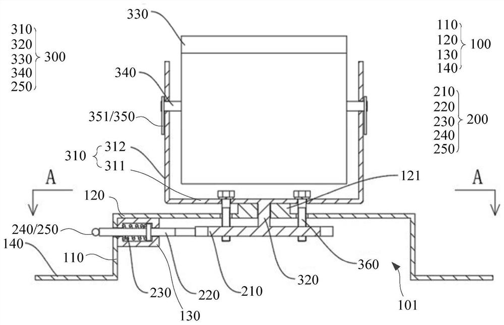
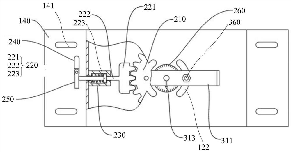
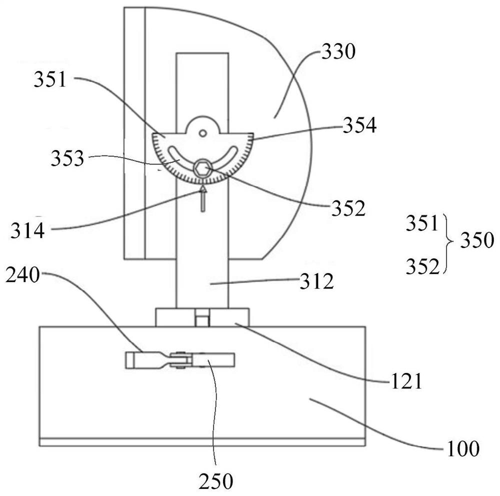
The invention provides a spotlight antenna convenient for angle adjustment, and relates to the technical field of communication facilities. The spotlight antenna convenient for angle adjustment comprises a base, a first angle adjusting assembly and an antenna assembly, wherein the base is provided with an accommodating cavity and a first connecting hole communicated with the accommodating cavity; the first angle adjusting assembly comprises a gear disc, a clamping pin and an elastic piece which are matched with one another; the gear disc is accommodated in the accommodating cavity; the clamping pin can slide in the radial direction of the gear disc; the elastic piece is used for enabling the clamping pin to be partially inserted into a tooth groove of the gear disc so as to lock the gear disc; the antenna assembly comprises an antenna body and a first rotating shaft connected with the antenna body; and the antenna body is located on the outer side of the base, and the first rotating shaft penetrates through the first connecting hole and is coaxially connected with the gear disc. According to the spotlight antenna convenient for angle adjustment, the installation and debugging efficiency of the spotlight antenna can be improved.

Description

technical field [0001] The present disclosure relates to the technical field of communication facilities, and in particular, to a spotlight antenna that facilitates angle adjustment. Background technique [0002] With the rapid development of mobile communications, in order to provide higher-quality network communication effects, communication operators usually use spotlight antennas to increase network coverage. During use, the communication operator will adjust the angle of the spotlight antenna according to the usage of the on-site network and the demand of the on-site network. In the prior art, the spotlight antenna is usually installed and fixed on the wall or the bracket according to the position after the on-site debugging after the commissioning is completed; According to the network demand situation, adjust the angle and reinstall and fix according to the latest position and requirements. This makes it very inconvenient to adjust the angle of the spotlight antenna...

Claims


Application Information

Patent Timeline
Patent Type & Authority Applications(China)
IPC IPC(8): H01Q1/22H01Q3/06
CPCH01Q1/22H01Q3/06Y02B20/40
Inventor 郭学涛岐剑万云飞
Owner CHINA TELECOM CORP LTD
Why Eureka
Eureka Blog
Learn More