Nuclear power station alternating-current power distribution debugging intelligent robot

An intelligent robot and AC power distribution technology, which is applied in circuit breaker testing, measuring resistance/reactance/impedance, instruments, etc., can solve the problems of single equipment debugging, low installation efficiency, high labor intensity, etc., and achieve convenient detection Fast and improve the efficiency of debugging and installation

Pending Publication Date: 2020-12-15
NORTH CHINA ELECTRIC POWER UNIV (BAODING)
View PDF0 Cites 0 Cited by
  • Summary
  • Abstract
  • Description
  • Claims
  • Application Information

AI Technical Summary

Problems solved by technology

[0003] The existing intelligent robots for AC power distribution debugging in nuclear power plants generally only have the function of debugging the equipment. After the equipment is debugged, it needs to be manually moved and installed. The labor intensity is high and the installation efficiency is low, so it cannot meet the needs of users.

Method used


Image

  • Nuclear power station alternating-current power distribution debugging intelligent robot
  • Nuclear power station alternating-current power distribution debugging intelligent robot
  • Nuclear power station alternating-current power distribution debugging intelligent robot

Examples


Embodiment 1

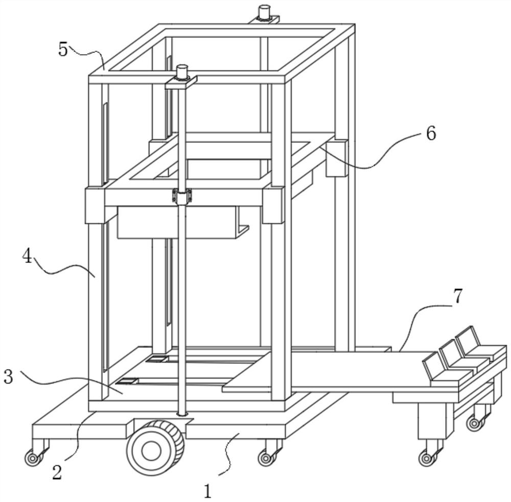
[0029] Embodiment one: refer to Figure 1-7 , including a mobile chassis 1, a framed manipulator 2 and a detection platform 7;

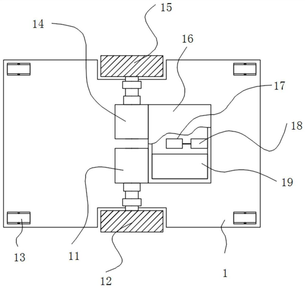
[0030] The bottom of the mobile chassis 1 is fixed with a left wheel motor 11 and a right wheel motor 14 by bolts along the center line of the width direction, the left drive wheel 12 is fixed by bolts on the output shaft of the left wheel motor 11, and the bolt is fixed on the output shaft of the right wheel motor 14. The right driving wheel 15, the left wheel motor 11 and the right wheel motor 14 are on the same horizontal line, and the four corners at the bottom of the mobile chassis 1 are bolted with the first auxiliary roller 13;

[0031] The upper surface of the mobile chassis 1 is provided with a frame-type manipulator 2. The frame-type manipulator 2 includes a base plate 3, a vertical rod 4 and a rectangular frame 5. The base plate 3 is welded on the upper surface of the mobile chassis 1, and four corners of the upper surface of the base plat...

Embodiment 2

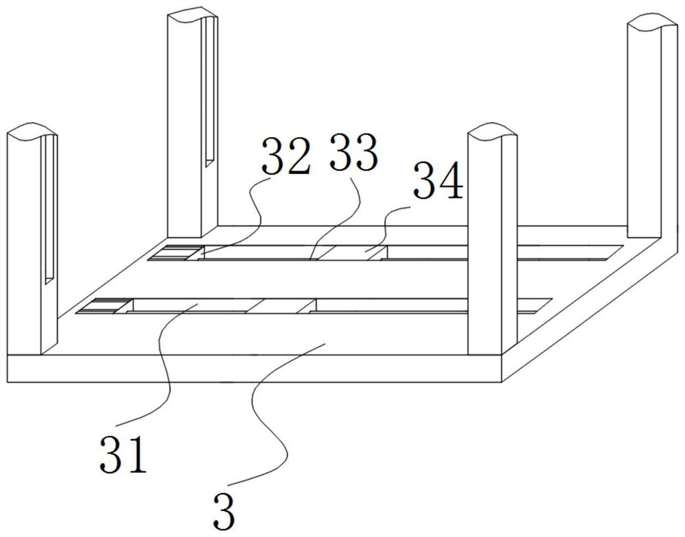
[0033] Embodiment two: refer to figure 1 , image 3 and Figure 7, the upper surface of the bottom plate 3 is provided with a strip groove 31 along the length direction, and a first lead screw motor 32 is fixed to one end bolt along the length direction on the inner substrate of the strip groove 31, and the output shaft of the first lead screw motor 32 is The first leading screw 33 is connected with rotation through the shaft coupling, the first leading screw nut seat 34 is screwed on the first leading screw 33, and the first leading screw nut seat 34 is fixed with the detection plate 71 bolts, the width of the detection plate 71 Less than the width of the base plate 3, the length of the detection plate 71 is greater than the length of the base plate 3, the first lead screw motor 32 is used to drive the first lead screw 33 to rotate, and the first lead screw 33 rotates, which can drive the first lead screw 33 on the first lead screw The first lead screw nut seat 34 moves, an...

Embodiment 3

[0034] Embodiment three: refer to figure 1 , Figure 4 and Figure 5 , the rectangular frame 5 is welded with a fixed seat, and the bolt on the fixed seat is fixed with a second lead screw motor 51, and the output shaft of the second lead screw motor 51 is connected with a second lead screw 52 through a shaft coupling. The second lead screw nut seat 61 is threaded on the bar 52, and the second lead screw nut seat 61 bolts are fixed on the outer wall of the rectangular lifting frame 6, and the second lead screw 52 is provided with two altogether, and two second lead screw nut seats The rod 52 is mutually symmetrical with respect to the frame-type manipulator 2. The bottom end of the second lead screw 52 is sleeved with a sleeve, and the sleeve is welded and fixed on the mobile chassis 1. The second lead screw motor 51 is used to drive the second lead screw 52 to rotate. , the rotation of the second leading screw 52 can drive the second leading screw nut seat 61 to move up and...


PUM


Abstract

The invention discloses a nuclear power station alternating-current power distribution debugging intelligent robot. The robot comprises a mobile chassis, a frame type manipulator and a detection platform, a left wheel motor and a right wheel motor are fixed to the bottom of the mobile chassis along the center line of the width direction through bolts, a left driving wheel is fixed to the output shaft of the left wheel motor through a bolt, and a right driving wheel is fixed on the output shaft of the right wheel motor through a bolt; and first auxiliary rolling wheels are fixed to the four corners of the bottom of the movable chassis through bolts. According to the nuclear power station alternating-current power distribution debugging intelligent robot, equipment can be debugged through the detection platform, position adjustment and angle adjustment can be automatically carried out on the debugged equipment through arrangement of the movable chassis, and the equipment with the adjusted position can be automatically lifted and pushed into an equipment mounting frame through the frame type manipulator, debugging and moving conveying of the equipment are integrally completed, and thedebugging and mounting efficiency of the equipment is improved to the maximum extent.

Description

technical field [0001] The invention relates to the technical field of AC power distribution in nuclear power plants, in particular to an intelligent robot for debugging AC power distribution in nuclear power plants. Background technique [0002] A nuclear power plant refers to a facility that converts nuclear energy into electrical energy through appropriate devices. Nuclear power plants use nuclear reactors instead of boilers in thermal power plants, and use nuclear fuel to generate heat in a special form of "combustion" in nuclear reactors, turning nuclear energy into thermal energy to heat water and generate steam. The systems and equipment of a nuclear power plant usually consist of two parts: nuclear systems and equipment, also known as nuclear islands; conventional systems and equipment, also known as conventional islands. [0003] Existing intelligent robots for AC power distribution debugging in nuclear power plants generally only have the function of debugging equ...

Claims


Application Information

Patent Timeline
IPC IPC(8): G05D1/02G01R31/327G01R31/12G01R27/02B25J11/00B25J9/16
CPCB25J9/162B25J9/1666B25J11/00G01R27/02G01R31/12G01R31/327G05D1/0238G05D1/0257
Inventor 谢庆房静贾以静刘欢谢军
Owner NORTH CHINA ELECTRIC POWER UNIV (BAODING)
Why Eureka
Try Eureka