Fire-fighting equipment surface layer paint spraying equipment

A technology of spraying equipment and fire fighting equipment, applied in spray booths, coatings, spraying devices, etc., can solve the problems of low work efficiency and high labor intensity.

Inactive Publication Date: 2021-12-03
杨帅华
View PDF6 Cites 2 Cited by
  • Summary
  • Abstract
  • Description
  • Claims
  • Application Information

AI Technical Summary

Problems solved by technology

[0004] In order to overcome the shortcomings of low work efficiency and high labor intensity, the technical problem of the present invention is to provide a fire-fighting equipment surface painting equipment with high efficiency and reduced labor force

Method used


Image

  • Fire-fighting equipment surface layer paint spraying equipment
  • Fire-fighting equipment surface layer paint spraying equipment
  • Fire-fighting equipment surface layer paint spraying equipment

Examples


Embodiment 1

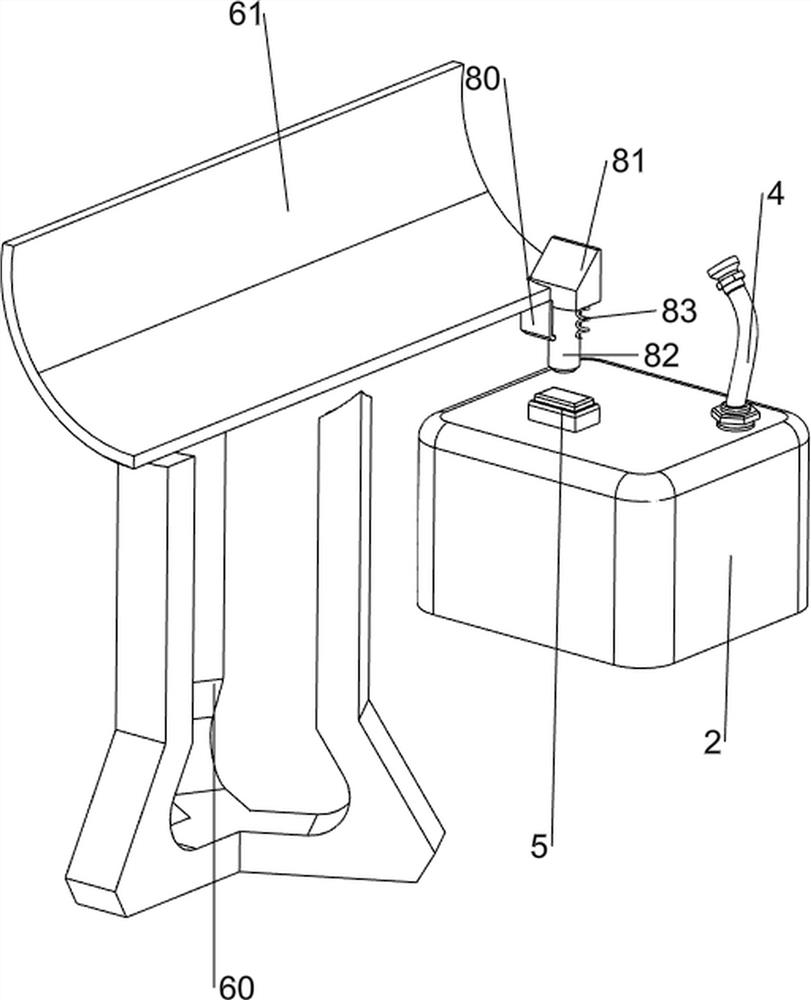
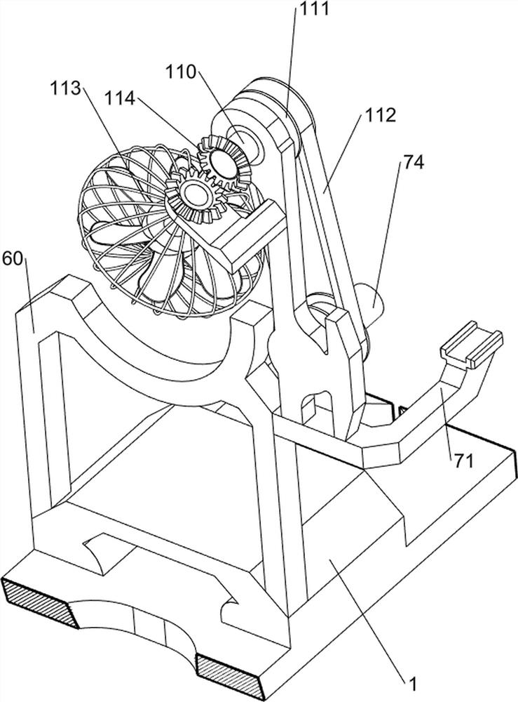
[0026] A kind of fire-fighting equipment surface layer painting equipment, such as Figure 1-Figure 4 As shown, it includes a shell 1, a paint box 2, a paint spray block 3, a hose 4, a switch 5, a push mechanism 6, a rotating mechanism 7 and a control mechanism 8, and the right part of the upper side of the shell 1 is connected with a paint box 2. The upper front part of the paint box 2 is connected with a hose 4, the upper side of the hose 4 is rotatably provided with a paint spraying block 3, the upper side of the paint box 2 is connected with a switch 5, and the upper right part of the casing 1 is provided with a push mechanism 6, and the casing The middle part of the upper side is provided with a rotating mechanism 7, and the inner lower side of the pushing mechanism 6 is connected with a control mechanism 8.

[0027] When the device needs to be used, the user can place the fire-fighting equipment in the push mechanism 6, start the push mechanism 6, and the push mechanism ...

Embodiment 2

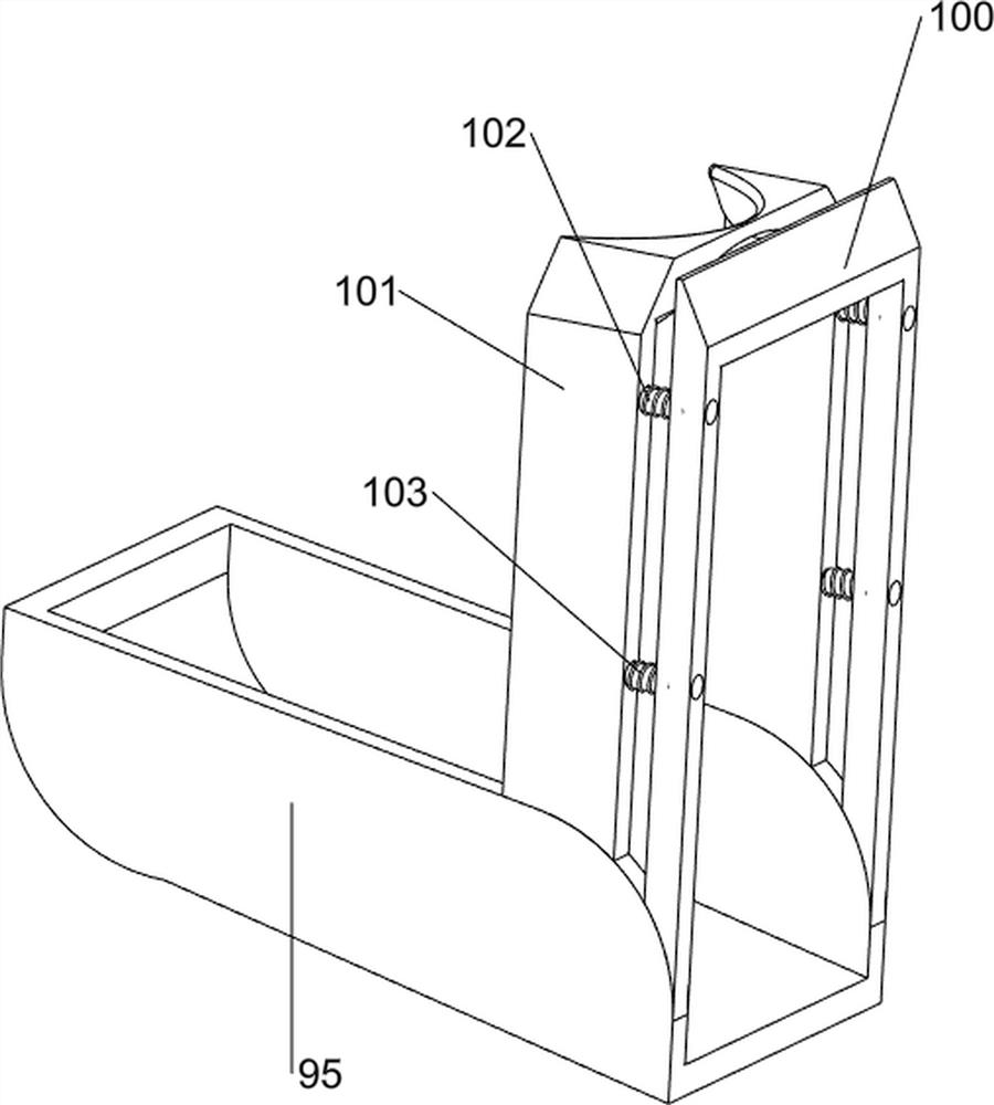
[0035] On the basis of Example 1, such as Figure 5-Figure 7 As shown, a feeding mechanism 9 is also included, and the feeding mechanism 9 includes a third support block 90, a feeding plate 91, a third rotating shaft 92, a second one-way gear 93, a second rack 94, and a support plate 95 And the toggle block 96, the left side of the upper part of the shell 1 is provided with a third support block 90, the upper side of the third support block 90 is connected with a feeding plate 91, the right side of the third support block 90 is provided with a support plate 95, and the support plate 95 Rotationally connected with a third rotating shaft 92, the third rotating shaft 92 is connected with a toggle block 96, the lower side of the third rotating shaft 92 is connected with a second one-way gear 93, and the left side of the first connecting block 63 is connected with a second one-way gear. The rack 94 , the second rack 94 cooperates with the second one-way gear 93 .

[0036] When the...


PUM


Abstract

The invention relates to paint spraying equipment, in particular to fire-fighting equipment surface layer paint spraying equipment. According to the technical aim, the fire-fighting equipment surface layer paint spraying equipment is high in efficiency and capable of reducing labor force. According to the technical scheme, the fire-fighting equipment surface layer paint spraying equipment comprises a shell, a paint containing box, a paint spraying block, a hose, a switch, a pushing mechanism, a rotating mechanism and a control mechanism. The paint containing box is connected to one side of the shell, the hose is connected to one side of the paint containing box, the paint spraying block is arranged on one side of the hose, and the switch is connected to one side of the paint containing box. The pushing mechanism is arranged on one side of the shell, the rotating mechanism is arranged on one side of the shell, and the control mechanism is connected to the lower side of the interior of the pushing mechanism. The fire-fighting equipment is driven by the pushing mechanism to slide rightwards, so that the fire-fighting equipment is in contact with the control mechanism, then the control mechanism slides downwards, and then the control mechanism slides downwards to be in contact with the switch.

Description

technical field [0001] The invention relates to a paint spraying device, in particular to a paint spraying device for the surface layer of fire fighting equipment. Background technique [0002] Fire extinguishers are the most common fire-fighting equipment in daily life. According to the country, the surface of fire extinguishers should be painted with red paint. The traditional methods are generally manual spraying or painting with brushes. The work efficiency is low, and the surface of fire extinguishers When painting with paint, the staff need to be in close contact with the paint. Because there are many harmful substances in the paint, they will volatilize into the air, and for a long time, it will affect the health of the staff. Fire-fighting pipeline refers to the pipeline material used for fire-fighting, connecting fire-fighting equipment and equipment, and transporting fire-fighting water, gas or other media. Due to special needs, the thickness and material of fire-...

Claims


Application Information

Patent Timeline
Patent Type & Authority Applications(China)
IPC IPC(8): B05B16/20B05B13/04B05B13/02B05B12/02B05D3/04
CPCB05B16/20B05B13/0421B05B13/0447B05B13/0221B05B12/02B05D3/0406
Inventor 杨帅华
Owner 杨帅华
Why Eureka
Try Eureka