Automobile part machining device
A processing device and technology for auto parts, applied in the field of parts processing, can solve problems such as paint splashing everywhere
- Summary
- Abstract
- Description
- Claims
- Application Information
AI Technical Summary
Problems solved by technology
Method used
Image
Examples
Embodiment 1
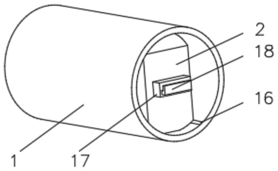
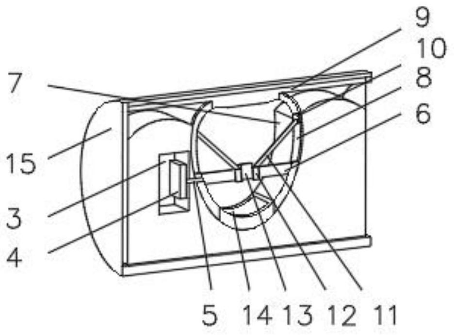
[0034] see Figure 1-4 , the present invention provides a technical solution: a processing device for automobile parts, comprising a casing 1, the casing 1 is a cylinder, the inside of the casing 1 is equipped with a device frame 2, the inside of the device frame 2 is provided with a groove 3, the groove 3 The first motor 4 is installed inside, the output shaft of the first motor 4 is rotatably connected with a rotating rod 5, and the end of the rotating rod 5 away from the motor 4 is fixedly connected with a rotating column 6, and one side of the device frame 2 is provided with a circular groove 7 , the inner wall of the circular groove 7 is symmetrically installed with a slide rail 8, the end of the slide rail 8 away from the circular groove 7 is fixedly connected to the top plate 9, the inside of the slide rail 8 is installed with a slider 10, and the slider 10 is far away from the end of the slide rail 8 The side is fixedly connected with a support 11, and the end of the s...
Embodiment 2
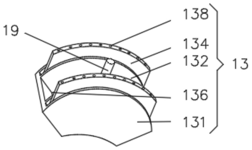
[0042] see Figure 1-5 , the present invention provides a technical solution: on the basis of Embodiment 1, a respray device 19 is installed inside the paint spraying device 13, and the respray device 19 includes an outer frame 191, and the outer frame 191 is connected with the fan-shaped groove 132, and the outer frame 191 Rotating block 192 is installed on the inner top of the rotating block 192, and a baffle plate 193 is installed symmetrically on one side of the rotating block 192. One end of the baffle plate 193 runs through a paint spray pipe 194, and one end of the paint spray pipe 194 is equipped with an atomizing nozzle 195. The bottom of the paint spray pipe 194 Be connected with the second paint spray pipe 196, one end of the second paint spray pipe 196 communicates with the paint bucket 136, a second air pump 197 is installed on one side of the second paint spray pipe 196, and a second motor 198 is installed at the bottom of the outer frame 191. The second motor 19...
Embodiment 3
[0045] see Figure 1-6 , the present invention provides a technical solution: on the basis of Embodiment 2, a quick-drying device 14 is installed on the bottom of the circular groove 7, and the quick-drying device 14 includes a quick-drying frame 144, and the inner bottom of the quick-drying frame 144 is installed with a second Three motors 141, the output shaft of the third motor 141 is rotatably connected to a rotating rod 142, one end of the rotating rod 142 is fixedly connected to a fan blade 143, and the inner arm of the quick-drying frame 144 is installed at a position far away from the third motor 141. Condensation and dehumidification pipe 145 .
[0046] When in use, turn on the third motor 141, drive the fan blade 143 to start rotating through the rotating rod 142, and then generate the flow of air. The installation can accelerate the air-drying of the paint, prevent the wet paint from affecting the painting effect of the nut, and facilitate the operation of the staf...
PUM
 Abstract
Description
Claims
Application Information
 - R&D
- Intellectual Property
- Life Sciences
- Materials
- Tech Scout
- Unparalleled Data Quality
- Higher Quality Content
- 60% Fewer Hallucinations
Browse by: Latest US Patents, China's latest patents, Technical Efficacy Thesaurus, Application Domain, Technology Topic, Popular Technical Reports.
© 2025 PatSnap. All rights reserved.Legal|Privacy policy|Modern Slavery Act Transparency Statement|Sitemap|About US| Contact US: help@patsnap.com


