Movable dust removal and purification equipment for cement production
A mobile dust removal and purification equipment technology, applied in cleaning equipment, applications, household appliances, etc., can solve the problems of poor cleaning effect and low work efficiency, and achieve the effect of increasing speed and improving work efficiency
- Summary
- Abstract
- Description
- Claims
- Application Information
AI Technical Summary
Problems solved by technology
Method used
Image
Examples
Embodiment 1
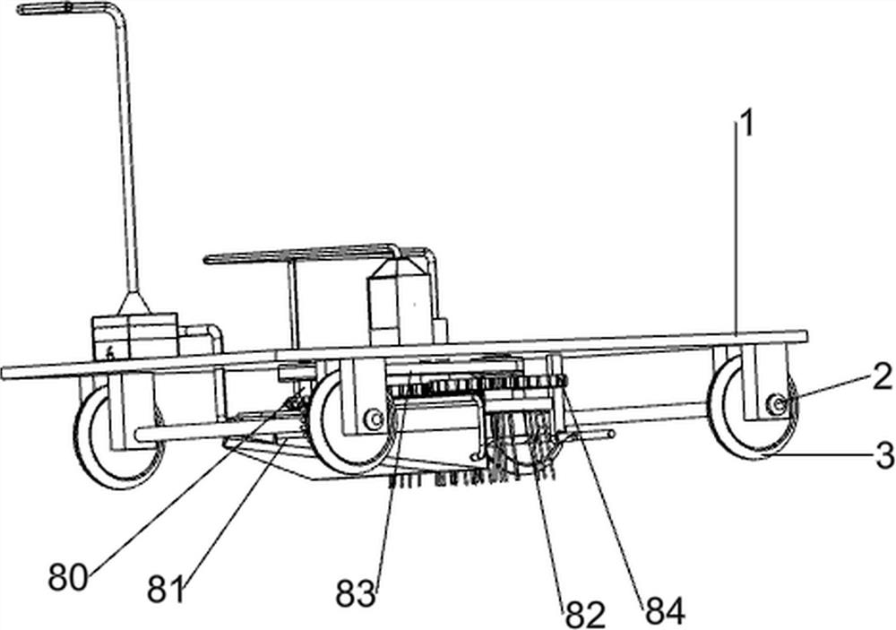
[0104] A mobile dust removal and purification equipment for cement production, such as figure 1 Shown, include base plate 1, first rotating shaft 2, wheel 3, first handle 4, dedusting mechanism 5 and spraying mechanism 6, bottom plate 1 bottom left and right sides symmetrical rotation type is provided with first rotating shaft 2, the first rotating shaft The front and rear sides of 2 are all provided with wheels 3, the left side of base plate 1 top is provided with first handle 4, the right side of base plate 1 top is provided with dedusting mechanism 5, and the left side of base plate 1 top is provided with spray mechanism 6.
[0105] When people need to remove dust and purify the air in the cement production plant, push the first handle 4, under the action of the rotation of the first rotating shaft 2 and the wheel 3, push the device to the working place, and then open a certain part of the dust removal mechanism 5 And the switch of spraying mechanism 6, dust removal mechani...
Embodiment 2
[0107] On the basis of Example 1, such as figure 2 , image 3 , Figure 4 , Figure 5 , Figure 6 , Figure 7 , Figure 8 , Figure 9 , Figure 11 and Figure 12 As shown, the dust removal mechanism 5 includes a support rod 50, a baffle plate 51, a first support plate 52, a filter element 53, a guide frame 54, an ash bucket 55, a second support plate 56, an ash bucket 57, a first air intake pipe 58, The first vacuum cleaner 59, the first fixed block 510, the dustpan 511, the second air intake pipe 512, the second vacuum cleaner 513, the second fixed block 514, the first air outlet pipe 515, the air bag 516 and the pulse solenoid valve 517, bottom plate 1 top right Support rods 50 are evenly arranged on the sides, and baffle plates 51 are arranged between the tops of the support rods 50. Two first support plates 52 are arranged on the left and right sides of the inside of the baffle plate 51, and two first support plates 52 are evenly arranged between the first support...
Embodiment 3
[0114] On the basis of Example 2, such as Figure 10 , Figure 13 , Figure 14 and Figure 15 As shown, a rotating mechanism 7 is also included, and the rotating mechanism 7 includes a third rotating shaft 70, a third rotating rod 71, a second spur gear 73, a first spur gear 72, a second clamping block 74, and a second rotating disk 75 , rotating block 76, the third supporting block 77 and the fourth rotating shaft 78, the top of the brush assembly 82 on the front side passes through the front left part of the bottom of the base plate 1, the top of the brush assembly 82 is provided with the third rotating shaft 70, placed Case 60 top right middle rotating type is provided with the 3rd rotating rod 71, and the 3rd rotating shaft 70 tops is provided with the first spur gear 72, and the 3rd rotating rod 71 middle part is provided with the 2nd spur gear 73, and the first spur gear 72 and The second spur gear 73 meshes with each other, the third rotating rod 71 bottom is provide...
PUM
 Abstract
Description
Claims
Application Information
 - R&D
- Intellectual Property
- Life Sciences
- Materials
- Tech Scout
- Unparalleled Data Quality
- Higher Quality Content
- 60% Fewer Hallucinations
Browse by: Latest US Patents, China's latest patents, Technical Efficacy Thesaurus, Application Domain, Technology Topic, Popular Technical Reports.
© 2025 PatSnap. All rights reserved.Legal|Privacy policy|Modern Slavery Act Transparency Statement|Sitemap|About US| Contact US: help@patsnap.com


