Driving method of array substrate, array substrate and display panel

A technology of an array substrate and a driving method, applied in the field of an array substrate, a display panel, and a driving method of an array substrate

Active Publication Date: 2021-12-03
BEIHAI HKC OPTOELECTRONICS TECH CO LTD +1
View PDF6 Cites 0 Cited by
  • Summary
  • Abstract
  • Description
  • Claims
  • Application Information

AI Technical Summary

Problems solved by technology

[0004] The main purpose of this application is to propose an array substrate, which aims to...

Method used


Image

  • Driving method of array substrate, array substrate and display panel
  • Driving method of array substrate, array substrate and display panel
  • Driving method of array substrate, array substrate and display panel

Examples


Embodiment Construction

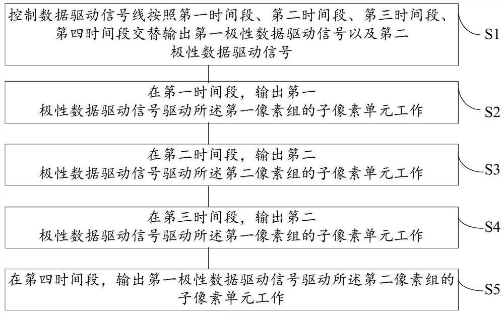
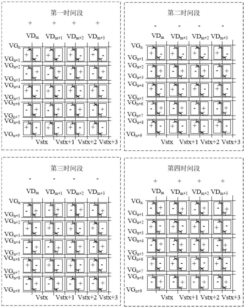
[0049] The technical solution in the embodiment of the application will be clearly and completely described below in conjunction with the accompanying drawings in the embodiment of the application. If there are descriptions involving "first", "second", etc. The descriptions of "first", "second" and so on are for descriptive purposes only, and should not be understood as indicating or implying their relative importance or implying the number of indicated technical features. Thus, the features defined as "first" and "second" may explicitly or implicitly include at least one of these features.

[0050] The present application proposes an array substrate, aiming at solving the technical problem that the array substrate easily produces bright and dark stripes.

[0051] In one embodiment, the solution of the present application is implemented based on an array substrate, such as figure 2 as well as Figure 4 As shown, the array substrate includes a plurality of sub-pixels arrange...


PUM


Abstract

The invention discloses a driving method of an array substrate, the array substrate and a display panel, the array substrate comprises a plurality of sub-pixels, a plurality of line scanning driving signal lines, a plurality of data driving signal lines and a plurality of common electrode signal lines, the sub-pixels are arranged in an array, each line of sub-pixels is divided into a first pixel group and a second pixel group, and each line of sub-pixels is divided into a plurality of first pixel groups and a plurality of second pixel groups. The sub-pixels in the first pixel group and the sub-pixels in the second pixel group are alternately arranged along the row where the sub-pixels are located, and each data driving signal line is arranged between two columns of sub-pixels in each group and electrically connected with each sub-pixel in the two columns of sub-pixels in each group. And each common electrode signal line is arranged between two adjacent groups of sub-pixels. According to the scheme, the technical problem that the array substrate easily generates bright and dark stripes is solved.

Description

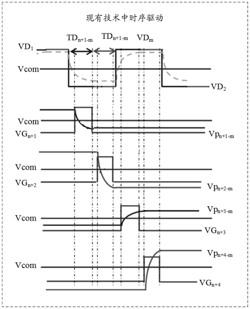
technical field [0001] The present application relates to the technical field of array substrates, in particular to a driving method of the array substrate, the array substrate and a display panel. Background technique [0002] The driving principle of the array substrate in the prior art is generally polarity inversion driving, that is, the liquid crystal molecules change their positional relationship by changing the voltage, and the polarity inversion driving is realized by applying a voltage signal with positive and negative polarity changes to the liquid crystal molecules. AC drive of liquid crystal molecules. The polarity inversion driving includes row inversion driving, column inversion driving, frame inversion driving and dot inversion driving. [0003] This application proposes based on polarity inversion. When the same row of pixel units is driven by two rows of scanning lines, since the driving time of the array substrate remains unchanged, and the row scanning li...

Claims


Application Information

Patent Timeline
IPC IPC(8): G09G3/36
CPCG09G3/3611G09G3/3614G09G2320/0233G09G2320/0252G09G2310/0221G09G2300/0452G09G2300/0426G09G2300/0842G09G2310/08G09G2320/0626
Inventor 康志聪袁海江
Owner BEIHAI HKC OPTOELECTRONICS TECH CO LTD
Why Eureka
Try Eureka