Drainage device for cardiovascular medicine

A cardiovascular and internal medicine technology, applied in the field of cardiovascular internal medicine equipment, can solve the problem that electric drive and human drive cannot coexist, achieve high drainage efficiency and ensure drainage efficiency

Inactive Publication Date: 2021-12-07
李旭
View PDF0 Cites 0 Cited by
  • Summary
  • Abstract
  • Description
  • Claims
  • Application Information

AI Technical Summary

Problems solved by technology

[0003] The invention provides a drainage device for cardiovascular medicine, which can solve the technical problem that electric drive and human drive cannot coexist

Method used


Image

  • Drainage device for cardiovascular medicine
  • Drainage device for cardiovascular medicine

Examples


Embodiment Construction

[0015] The following descriptions are only preferred embodiments of the present invention, and do not limit the protection scope of the present invention. The present invention will be further described below in conjunction with the accompanying drawings and embodiments.

[0016] Examples, see Figure 1 to Figure 2 Shown:

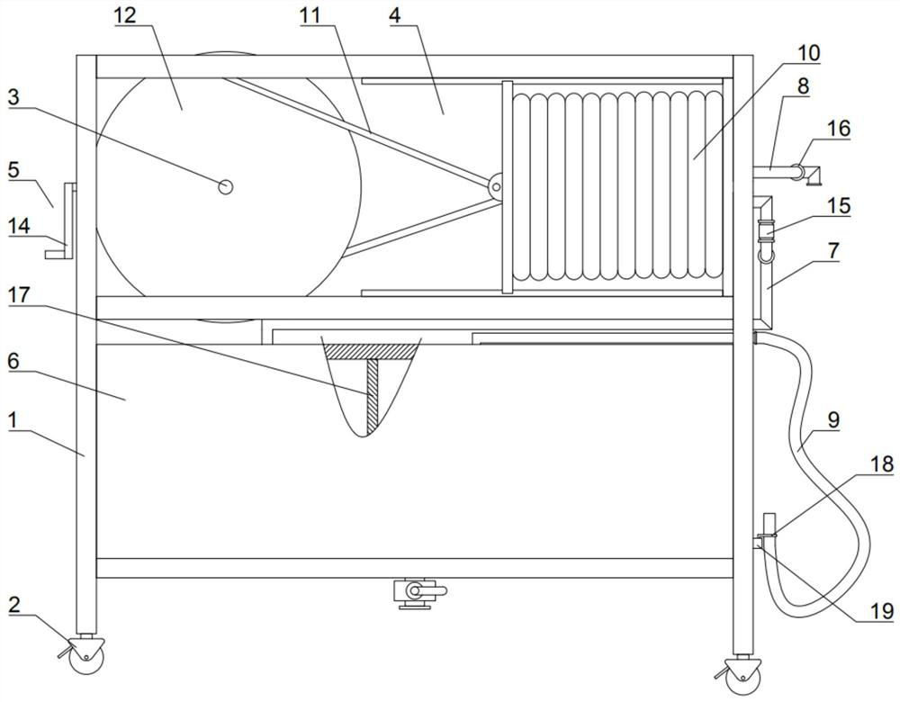
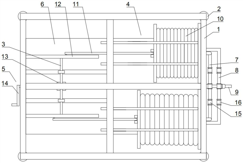
[0017] A drainage device for cardiovascular medicine, comprising a drainage frame 1, a universal wheel with a brake mechanism 2, a linkage shaft 3, two sets of suction mechanisms 4, a driving mechanism 5, a liquid storage tank 6, a suction pipe 7, a drainage Trachea 8 and drainage tube 9, described universal wheel 2 is fixedly installed on the bottom of described drainage frame 1, and universal wheel 2 should be four, and four universal wheels 2 are evenly distributed on the bottom of drainage frame 1, drainage The frame 1 moves through the universal wheels 2, and at the same time, the positioning of the drainage frame 1 is realized through the braking mec...


PUM


Abstract

The invention discloses a drainage device for cardiovascular medicine, which is characterized by comprising a drainage frame, a universal wheel with a brake mechanism, a linkage shaft, two groups of air suction mechanisms, a driving mechanism, a liquid storage tank, an air suction pipe, an exhaust pipe and a drainage pipe, each air suction mechanism comprises an air bag, a linkage rod and a wheel disc, when the linkage shaft rotates, the linkage shaft enables the top plates of the two air bags to move in opposite directions, and comprises a driving motor and a driving rod. Compared with the prior art, the drainage device has the advantages that negative pressure is generated in the liquid storage tank through cooperation of the air bags, the linkage rod, the linkage shaft and other components, drainage is achieved, the drainage efficiency is high, the drainage speed is easy to adjust, through cooperation of the driving motor, the driving rod and other parts, coexistence of electric driving and manual driving is achieved, and the situation that drainage cannot be achieved due to power failure and other emergencies is avoided while the overall drainage efficiency is guaranteed.

Description

technical field [0001] The invention relates to the technical field of equipment for cardiovascular medicine, in particular to a drainage device for cardiovascular medicine. Background technique [0002] In the treatment of cardiovascular diseases, drainage equipment is an indispensable treatment device, which plays an important role in drawing out the body fluid accumulated in the patient's subcutaneous or cavity. Most of the existing drainage equipment is driven by electricity or manpower to generate negative pressure. , and then suck the body fluid into the liquid storage bottle through negative pressure. Although this structure can achieve drainage, it also has certain shortcomings. For electric drive, when the power is insufficient, or the number of sockets is insufficient, or the electric drive components are damaged, it cannot This will undoubtedly cause greater harm to patients who are in urgent need or are being drained. At the same time, for human drive, its effici...

Claims


Application Information

Patent Timeline
Patent Type & Authority Applications(China)
IPC IPC(8): A61M1/00
CPCA61M2209/082
Inventor 李旭刘波
Owner 李旭
Why Eureka
Try Eureka