An experimental system and steady -state experimental method for measuring the heat exchange coefficient of the leaf leaf top

A technology of heat transfer coefficient and experimental system, applied in the field of gas turbine blade design, can solve the problems of poor repeatability of experimental results, difficult gap size, inapplicability, etc., to improve flexibility, good repeatability, and reduce processing costs. Effect

Active Publication Date: 2022-08-05
XI AN JIAOTONG UNIV
View PDF11 Cites 0 Cited by
  • Summary
  • Abstract
  • Description
  • Claims
  • Application Information

AI Technical Summary

Problems solved by technology

[0003] At present, there are few experimental platforms for measuring the heat transfer coefficient of the blade tip, and its design is mainly reflected in the following aspects: 1. The gap between the blade tip of the real gas turbine turbine blade is extremely small, usually 1 to 2 mm, and the gap of the aero-engine The blade tip gap is smaller, usually around 0.5 mm, and it is difficult to ensure a reasonable gap size in the experimental design; 2. Due to the limitation of the blade tip gap, the traditional heat transfer coefficient measurement method of attaching a heating film on the surface is not suitable for blade tip clearance. It is necessary to find a new measurement method; 3. At present, almost all the experimental platforms for measuring the heat transfer coefficient of the blade top adopt the transient thermochromic liquid crystal measurement method, and the repeatability of the experimental results is not good.

Method used


Image

  • An experimental system and steady -state experimental method for measuring the heat exchange coefficient of the leaf leaf top
  • An experimental system and steady -state experimental method for measuring the heat exchange coefficient of the leaf leaf top
  • An experimental system and steady -state experimental method for measuring the heat exchange coefficient of the leaf leaf top

Examples


Embodiment Construction

[0031] The following is combined with the attachment and embodiments to explain the implementation of the present invention in detail.

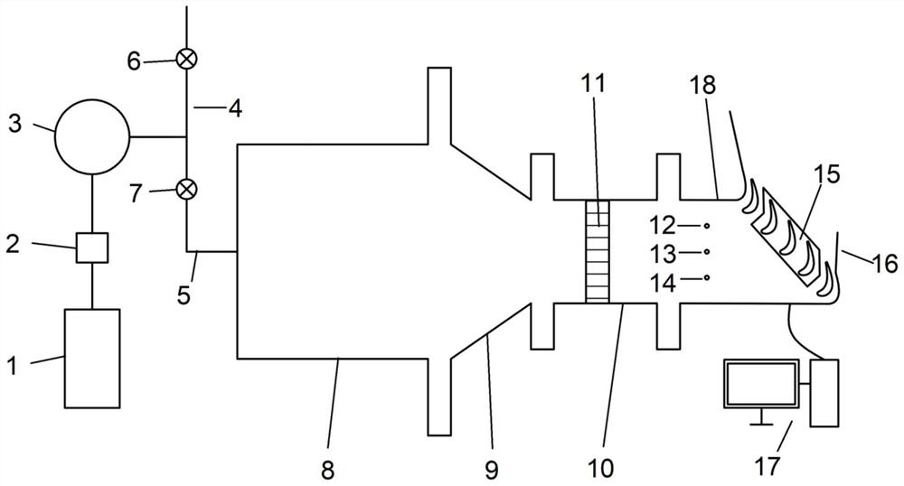
[0032] like figure 1 It is shown that the present invention is a experimental system for measuring the thermal coefficient of the leaf leaf top, which mainly includes the air supply device and the test section 18. There is a gap between the leaves of the blades and the wall surface of the test section 18. One of the blades in the middle is used as the measurement of the blade 22, the air supply device is available to the test section 18 The gap between the section 18 flows flows.

[0033] In one embodiment, the air supply device includes an air compressor connected in turn 1., gas cooling dryer 2 and gas storage tank 3. The exit of the gas storage tank 3 is divided into two roads, connecting the bypass pipeline 4 and the mainstream pipeline 5 respectively. Essence

[0034] Mainstream pipeline 5 is connected to the test section 18. Specific land c...


PUM


Abstract

An experimental system for measuring the heat transfer coefficient of a turbine blade tip. The outlet of the air supply device is connected to a bypass pipeline and a main flow pipeline, and the main flow pipeline is connected to a pressure stabilization section, a contraction section, and an intake section in turn. and the test section, wherein a rectifying honeycomb is set at the inlet end of the air inlet section, the test piece is set in the test section, and the test piece includes several blades, and there is a gap between the tip of each blade and the wall surface of the test section, and the middlemost blade is used as the test section. For the blade to be measured, infrared glass is arranged on the tip of the test section facing the blade to be measured, and an infrared thermal imager is placed above the infrared glass to measure the temperature distribution cloud map of the blade tip surface through the infrared glass. The invention also provides a steady-state experimental method based on the experimental system for measuring the heat transfer coefficient of the blade tip of a turbine moving blade, monitoring the flow parameters and temperature in the test section, and after the surface temperature of the replaceable blade tip is stabilized, according to Newton's law of cooling and Fourier's formula calculate the tip heat transfer coefficient.

Description

Technical field [0001] The present invention belongs to the field of gas turbine's blade design technology, and specially involves an experimental system and steady -state experimental method for measuring the thermal coefficient of the leaf leaf top. Background technique [0002] Gas turbine is an indispensable power device in modern industries. It is mainly used for power generation, ship power, aviation promotion, etc. In the leaf of the gas turbine, due to the existence of the gap between the leaf top, some mainstream will leak from the pressure surface from the pressure surface to the suction surface under the influence of the gap between the leaf roof. The region is suffering from a huge heat load, and it occurs from the top of the blade on the top of the blade. It has become one of the important reasons for the failure of turbine components. The safe and stable operation of the gas turbine. Therefore, the construction of the heating coefficient of the dynamic leaf top is t...

Claims


Application Information

Patent Timeline
Patent Type & Authority Patents(China)
IPC IPC(8): G01N25/20
CPCG01N25/20
Inventor 刘钊李冯贾哲王海锋张韦馨丰镇平
Owner XI AN JIAOTONG UNIV
Why Eureka
Try Eureka