Sound collection device

A sound collection device and sound technology, applied in the direction of loudspeakers, microphones, sensors, etc., can solve the problems of effective control of sound propagation path, insensitive and accurate sound collection, sensitive and rough, etc., to solve the problem of sound accumulation and transmission The effect of control, low cost and convenient use

Pending Publication Date: 2021-12-10
NANJING COLLEGE OF INFORMATION TECH
View PDF0 Cites 0 Cited by
  • Summary
  • Abstract
  • Description
  • Claims
  • Application Information

AI Technical Summary

Problems solved by technology

[0002] In daily life, sound is an important way to transmit information. How to collect sound and convert it into electrical signals to serve the control and transmission of sound is a subject of research and application. There are many common sound sensor methods, large and small, and sensitive. Rugged, with the miniaturization of electronic products, the requirements for sound acquisition devices are also smaller. A small sound acquisition chip based on MEMS technology is widely used, and its structure is also more. Due to its small size, it will always exist due to the influence of space position The main reason for the insensitivity and accuracy of sound collection is that the sound propagation path is not effectively controlled through the structural form. For this purpose, it is of practical significance to design a new structural sound collection chip for collection and transmission control.

Method used


Image

  • Sound collection device
  • Sound collection device
  • Sound collection device

Examples


Embodiment Construction

[0022] The present invention will be further described in detail below in conjunction with the accompanying drawings.

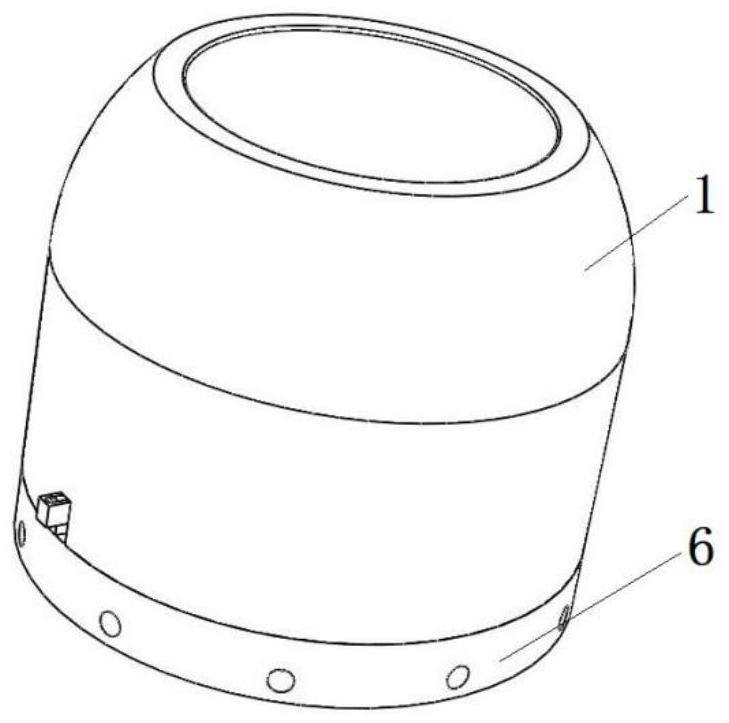
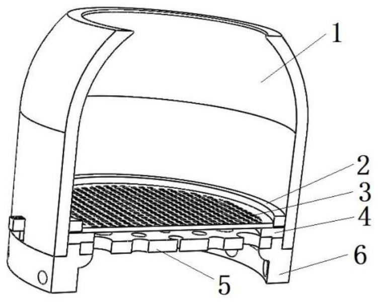
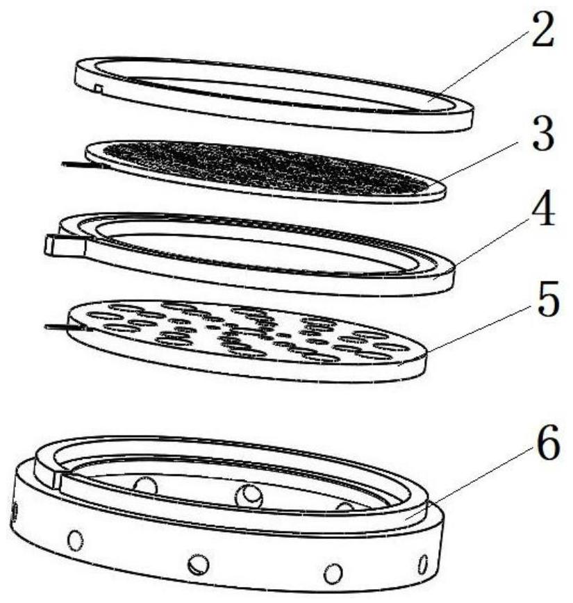
[0023] like Figure 1-8 As shown, the present invention discloses a sound collection device, which includes a sound collection cavity 1, in which an upper base plate 2, a diaphragm 3, a middle base plate 4, an electrode plate 5, and a lower base plate 6 are sequentially arranged from top to bottom. The sound collection chamber 1 includes a sound collection chamber 12, and a connection chamber 11 that is integrated with the sound collection chamber 12. The sound collection chamber 12 is an open hemisphere with an inner hollow, and the upper part is an open sound inlet, which is the sound inlet. Holes 13; the connecting warehouse 11 is a barrel-shaped structure, and the bottom of the connecting warehouse 11 is provided with a cross-sectional groove 14, and the sound collecting cavity 1 is embedded with the lower substrate 6 through the cross-sectional groove 14...


PUM


Abstract

The invention discloses a sound collection device which comprises a vibrating diaphragm provided with a lead terminal, a sound collection cavity covers the vibrating diaphragm, a polar plate with a through hole is arranged in the sound collection cavity in contact with the vibrating diaphragm, and a sound inlet of the sound collection cavity, the vibrating diaphragm and the through hole in the polar plate form a sound inlet and outlet channel. The sound inlet of the sound collection cavity, the vibrating diaphragm and the through hole in the polar plate form a sound inlet and outlet channel, so that the problems of sound collection and transmission control are effectively solved; the size, the shape and the position of the through hole in the polar plate are set, so that sound transmission is more facilitated; the vibrating diaphragm is integrated with the polar plate through the middle substrate, so that the transmission of vibration is more efficient and sensitive; the size, the shape and the position of the loudspeaker hole in the lower substrate are set, so that vibration can be transmitted outwards more easily; the device is simple in overall structure, low in cost and convenient to use.

Description

technical field [0001] The invention relates to a sound signal capturing device, in particular to a sound collecting device. Background technique [0002] In daily life, sound is an important way to transmit information. How to collect sound and convert it into electrical signals to serve the control and transmission of sound is a subject of research and application. There are many common sound sensor methods, large and small, and sensitive. Rugged, with the miniaturization of electronic products, the requirements for sound acquisition devices are also smaller. A small sound acquisition chip based on MEMS technology is widely used, and its structure is also more. Due to its small size, it will always exist due to the influence of space position The main reason for the insensitivity and accuracy of sound collection is that the sound propagation path is not effectively controlled through the structural form. For this purpose, it is of practical significance to design a new str...

Claims


Application Information

Patent Timeline
Patent Type & Authority Applications(China)
IPC IPC(8): H04R7/02H04R7/16
CPCH04R7/02H04R7/16H04R2201/02
Inventor 李微陈星
Owner NANJING COLLEGE OF INFORMATION TECH
Why Eureka
Try Eureka