
Cam control mechanism of continuous ejection clip applier

A technology of cam control and clamp applicator, which is applied in the field of medical equipment, can solve the problems of inconvenient operation, complex product structure, and poor matching of two-step clamping actions, and achieve the effect of convenient use and simple structure

Active Publication Date: 2021-12-17
HANGZHOU KANGJI MEDICAL INSTR
View PDF9 Cites 2 Cited by
  • Summary
  • Abstract
  • Description
  • Claims
  • Application Information

AI Technical Summary

Problems solved by technology

If the uniform-speed propulsion method adopted by the clamp applicator in the prior art is obviously not well matched with the two-step clamping action
However, if the applying action of the clip applicator chuck and the advancing action of the tissue clip are controlled by two sets of mechanisms respectively, the product structure will become very complicated and the operation will not be convenient enough.

Method used


Image

  • Cam control mechanism of continuous ejection clip applier
  • Cam control mechanism of continuous ejection clip applier
  • Cam control mechanism of continuous ejection clip applier

Examples


Embodiment Construction

[0034] The present invention will be described in further detail below in conjunction with the accompanying drawings and specific embodiments.

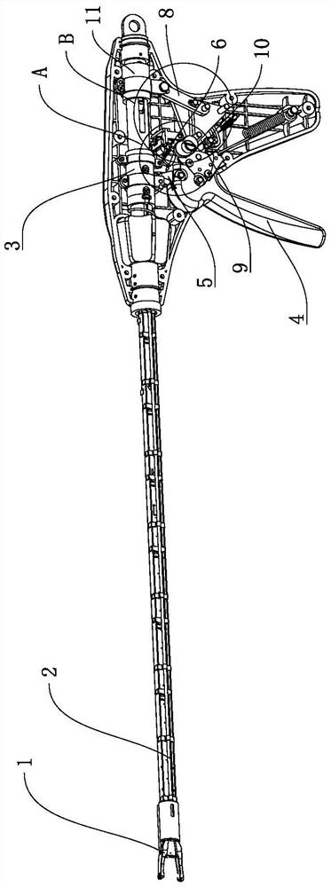
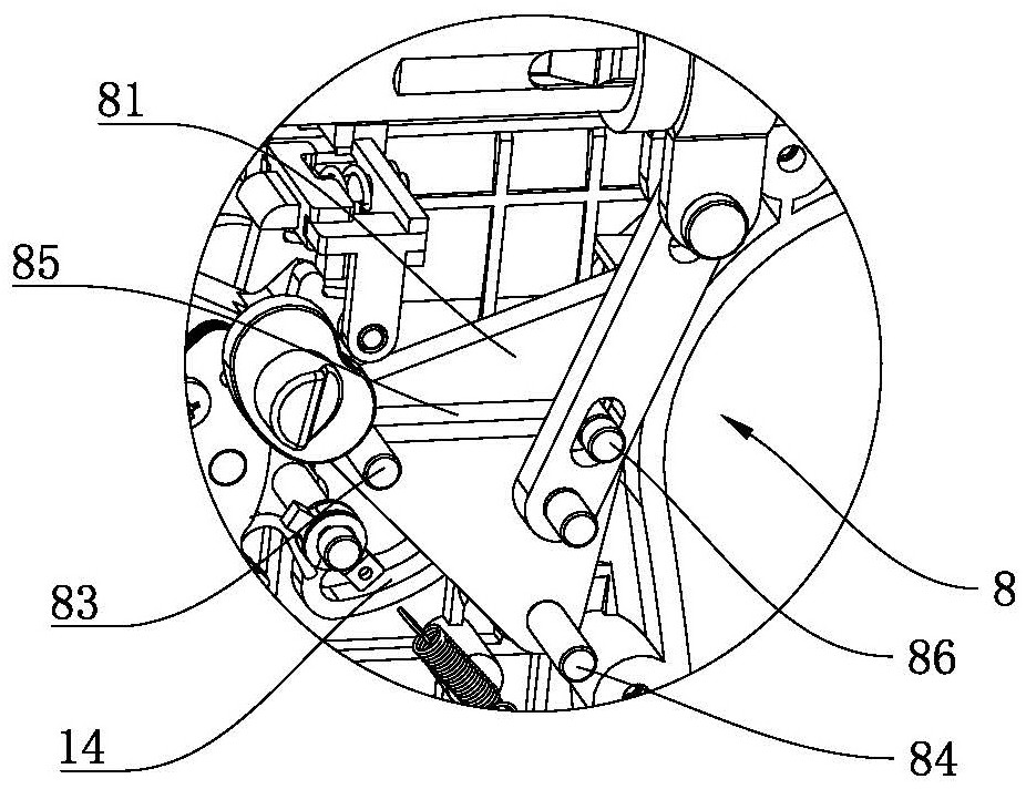
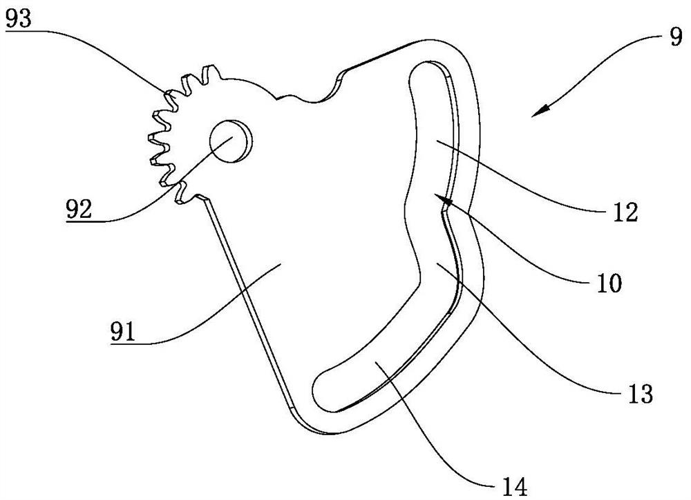
[0035] combine figure 1 with figure 2 As shown, a cam control mechanism of a continuous clip applicator includes a tissue clip advancing structure 11 for pushing the tissue clip, and also includes a driving handle 4, and one side of the driving handle 4 is provided with a driving connection with the driving handle 4. The special-shaped cam 9 is provided with a special-shaped groove 10 on the special-shaped cam 9, and the special-shaped groove 10 is composed of several arc segments with different distances from the center of rotation of the special-shaped cam 9. The special-shaped cam 9 and the tissue clip A transmission assembly 8 is arranged between the propulsion structures 11 , one end of the transmission assembly 8 is slidably connected in the special-shaped groove 10 , and the other end is rotatably connected to the tissue clip...


PUM


Abstract

The invention belongs to the technical field of medical instruments, and particularly relates to a cam control mechanism of a continuous ejection clip applier. In order to solve the problem that in the prior art, a constant-speed propelling mode adopted by a clip applier cannot be well matched with a two-step clamping action, the cam control mechanism of the continuous ejection clip applier is provided. The cam control mechanism comprises a tissue clip propelling structure and further comprises a driving handle; a special-shaped cam is arranged on one side of the driving handle; a special-shaped groove is formed in the special-shaped cam; the special-shaped groove is composed of a plurality of arc sections with different distances from the rotating center of the special-shaped cam; and a transmission assembly is arranged between the special-shaped cam and the tissue clip propelling structure. The special-shaped cam is provided with the special-shaped groove, and the special-shaped groove is composed of the plurality of arc sections with different distances from the rotating center of the special-shaped cam, so that the tissue clip propelling structure can obtain different propelling speeds in the constant-speed driving process of the driving handle, and the tissue clip propelling structure can be better suitable for the step-by-step clamping action of a clamp head.

Description

technical field [0001] The invention belongs to the technical field of medical instruments, and in particular relates to a cam control mechanism of a continuous clip applicator. Background technique [0002] A clip applier is a surgical instrument used to clamp tissue clips during surgery. Usually, the tissue clips can be made of metal materials, such as titanium clips, or other materials, such as plastic clips. When the tissue clip is being clamped, it is necessary to push the tissue clip out of the clip applier first, and then use the pliers head to close the tissue clip to achieve clamping. However, some tissue clips, such as plastic tissue clips, will have a large automatic springing action when they are pushed out to the position of the clamp applicator, which brings inconvenience to the medical staff during the operation. [0003] Therefore for this problem, the inventor tries to adopt the mode of step-by-step feeding to solve. That is, the two-step clamping of the ...

Claims


Application Information

Patent Timeline
Patent Type & Authority Applications(China)
IPC IPC(8): A61B17/128
CPCA61B17/128A61B2017/00367
Inventor 钟鸣程达孙学战唐文鹏
Owner HANGZHOU KANGJI MEDICAL INSTR
Learn More