Continuous ejection clip applying mechanism applied to continuous ejection clip applier

A technique for applying clips and clips, applied in the field of medical devices, can solve the problems of limited number of continuous clips, inconvenient use, longer length of clips, etc. the effect of efficiency

Pending Publication Date: 2021-12-17
HANGZHOU KANGJI MEDICAL INSTR
View PDF21 Cites 0 Cited by
  • Summary
  • Abstract
  • Description
  • Claims
  • Application Information

AI Technical Summary

Problems solved by technology

[0004] Although this invention patent application can realize continuous clip application, it is actually realized by increasing the space at the end for storing tissue clips. Other structures still adopt a structure similar to that of single clip applicators, which leads to The number of clips that can be applied in succession is extremely limited, and the overall length of the clip applicator will be significantly longer, which will bring inconvenience to use

Method used


Image

  • Continuous ejection clip applying mechanism applied to continuous ejection clip applier
  • Continuous ejection clip applying mechanism applied to continuous ejection clip applier
  • Continuous ejection clip applying mechanism applied to continuous ejection clip applier

Examples


Embodiment Construction

[0031] The present invention will be described in further detail below in conjunction with the accompanying drawings and specific embodiments.

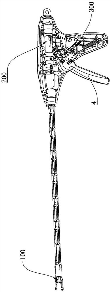
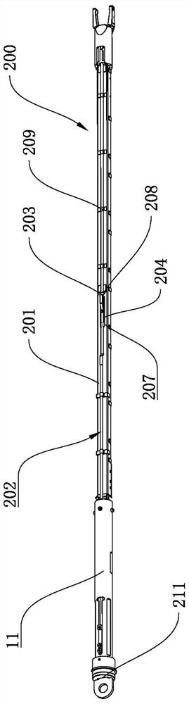
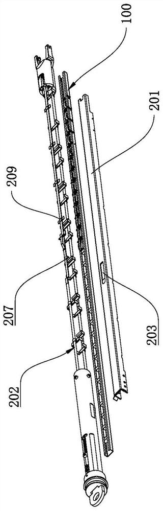
[0032] combine Figure 1-3 As shown, a continuous clip application mechanism applied to a continuous clip applicator includes a clip installation structure 200 installed on a clip applier housing 300, and the clip installation structure 200 includes a clip chamber 204 and an outer clip chamber 204. The push rod assembly 202, the clip assembly 100 capable of accommodating at least two tissue clips 102 is arranged in the clip chamber 204, and a part of the outer push rod assembly 202 extends into the clip chamber 204 and is pressed on the clip assembly 100 , the clip applier housing 300 is rotatably connected with a driving handle 4, the driving handle 4 is drivingly connected with the outer push rod assembly 202, and when the driving handle 4 is rotated, the driving handle 4 pushes the outer push rod assembly 202 to generate reciproca...


PUM


Abstract

The invention belongs to the technical field of medical instruments, and particularly relates to a continuous ejection clip applying mechanism applied to a continuous ejection clip applier. In order to solve the problem that the operation efficiency is relatively low as most clip appliers are single ejection clip appliers in the prior art, the invention provides the continuous ejection clip applying mechanism applied to the continuous ejection clip applier. The continuous ejection clip applying mechanism comprises a clip mounting structure mounted on a clip applier shell; the clip mounting structure comprises a clip cavity and an outer push rod assembly; a clip assembly capable of containing at least two tissue clips is arranged in the clip cavity; one part of the outer push rod assembly extends into the clip cavity and is pressed on the clip assembly; the clip applier shell is rotationally connected with a driving handle; and the driving handle is in driving connection with the outer push rod assembly. The clip assembly capable of preloading the plurality of tissue clips is independently arranged in the clip mounting structure, and the driving handle can be utilized to push the outer push rod assembly to sequentially eject out the tissue clips in the clip assembly for clip application in the operation process, so that continuous clip application is realized.

Description

technical field [0001] The invention belongs to the technical field of medical devices, and in particular relates to a continuous hair clamping mechanism applied to continuous hair clamping forceps. Background technique [0002] A clip applier is a surgical instrument used to clamp tissue clips during surgery. However, most of the clip appliers in the prior art are single-shot clip appliers, that is, tissue clips must be reinstalled at the clip head after each clip application, which results in lower operation efficiency. [0003] In response to this problem, people have also carried out exploration and research in long-term production and life practice. For example, a Chinese invention patent application discloses a continuous clamp application [Application No.: 201910733751.7]. The rod and the pincer head installed on the front end of the pipe rod also include a feeding device, a push-pull rod and a storage bin arranged in the pipe rod, and the feeding device includes a t...

Claims


Application Information

Patent Timeline
Patent Type & Authority Applications(China)
IPC IPC(8): A61B17/128
CPCA61B17/1285A61B2017/0046A61B2017/00398
Inventor 刘男周鹏程磊雷云
Owner HANGZHOU KANGJI MEDICAL INSTR
Why Eureka
Try Eureka