
Method for controlling suction pressure of a vapour compression system

A vapor compression, pressure technology, used in compressors with multiple evaporators, compressors, compressors, etc.

Active Publication Date: 2021-12-21
DANFOSS AS
View PDF6 Cites 0 Cited by
  • Summary
  • Abstract
  • Description
  • Claims
  • Application Information

AI Technical Summary

Problems solved by technology

However, when the vapor compression system is provided with a check valve, as is the case in the vapor compression system disclosed in WO 2016 / 188777 A1, there may be pressure in the part of the refrigerant path interconnected with the receiver and compressor unit risk of reaching unacceptable levels

Method used


Image

  • Method for controlling suction pressure of a vapour compression system
  • Method for controlling suction pressure of a vapour compression system
  • Method for controlling suction pressure of a vapour compression system

Examples


Embodiment Construction

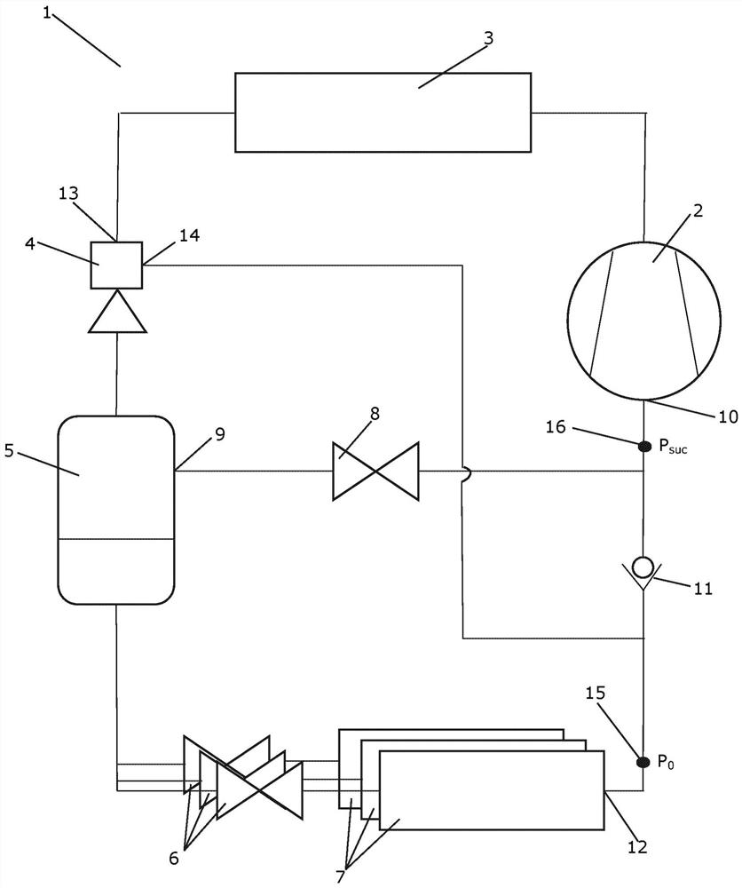
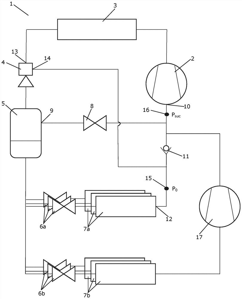
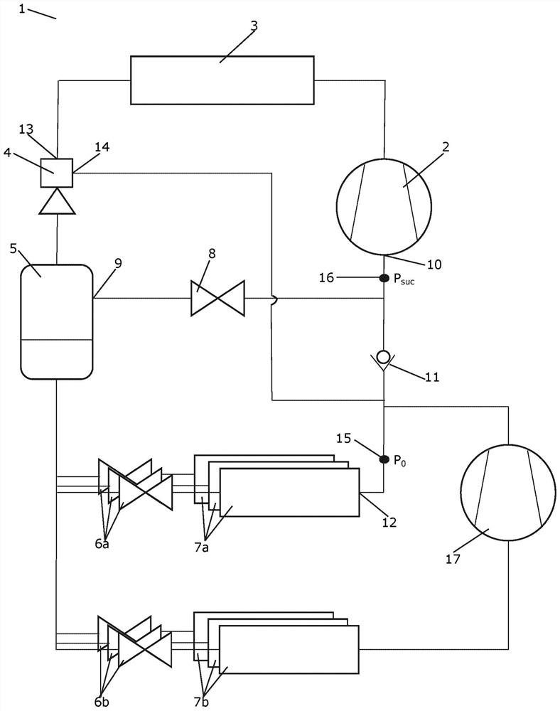
[0056] figure 1 is a diagrammatic view of a vapor compression system 1 operating according to a method according to a first embodiment of the invention. The vapor compression system 1 comprises a compressor unit 2 , a heat rejection heat exchanger 3 , an ejector 4 , a receiver 5 , three expansion devices 6 and three evaporators 7 arranged in a refrigerant path. The evaporators 7 are fluidly arranged in parallel, and each of the expansion devices 6 supplies refrigerant to one of the evaporators 7 . A bypass valve 8 interconnects the gas outlet 9 of the receiver 5 with the inlet 10 of the compressor unit 2 . A check valve 11 is arranged in the refrigerant path between the outlet 12 of the evaporator 7 and the inlet 10 of the compressor unit 2 .

[0057] The refrigerant flowing in the refrigerant path is compressed by the compressor unit 2 . The compressed refrigerant is supplied to the heat rejection heat exchanger 3, where heat exchange with the environment takes place in su...


PUM


Abstract

A method for controlling a vapour compression system (1) is disclosed. The vapour compression system (1) comprises an ejector (4), and has a non-return valve (11) arranged in the refrigerant path between an outlet (12) of an evaporator (7) and an inlet (10) of a compressor unit (2), in such a manner that a refrigerant flow from the outlet (12) of the evaporator (7) towards the inlet (10) of the compressor unit (2) is allowed, while a fluid flow from the inlet (10) of the compressor unit (2) towards the outlet (12) of the evaporator (7) is prevented. A pressure, P0, of refrigerant leaving the evaporator (7) is measured and a value being representative for a pressure, Psuc, of refrigerant entering the compressor unit (2) is obtained. The pressures, P0 and Psuc, are compared to respective reference pressure values, P0,ref and Psuc,ref. In the case that [epsilon]0>[epsilon]suc, wherein [epsilon]0=P0-P0 ,ref and [epsilon]suc=Psuc-Psuc,ref, the compressor unit (2) is controlled based on P0, and in the case that [epsilon]suc>[epsilon]0, the compressor unit (2) is controlled based on Psuc.

Description

technical field [0001] The invention relates to a method for controlling a vapor compression system comprising an ejector. The method of the present invention includes controlling a compressor unit of a vapor compression system in order to obtain a suitable suction pressure. Background technique [0002] In some vapor compression systems, the ejector is arranged at a downstream position in the refrigerant path relative to the heat rejection heat exchanger. Thereby, refrigerant leaving the heat rejection heat exchanger is supplied to the primary inlet of the ejector. Refrigerant exiting the evaporator of the vapor compression system may be supplied to the secondary inlet of the ejector. [0003] An ejector is a type of pump that uses the Venturi effect to increase the pressure energy of the fluid at the ejector's secondary inlet (or suction inlet) by means of motive fluid supplied to the ejector's primary inlet (or power inlet) . Thus, arranging the ejector in the refrige...

Claims


Application Information

Patent Timeline
IPC IPC(8): F25B9/08F25B31/00F25B39/02F25B41/20F25B49/02
CPCF25B9/08F25B31/00F25B39/02F25B41/20F25B49/02F25B2700/197F25B2600/2509F25B2500/19F25B1/10F25B41/00F25B5/02F25B2341/0012F25B2400/23F25B2700/1933F25B41/22
Inventor 简·普林斯拉斯·费恩斯洛特拉森
Owner DANFOSS AS
Learn More