Micro-trigger pen

A micro-trigger and displacement technology, applied in printing, writing utensils, writing parts, etc., can solve problems such as poor trigger sensitivity, and achieve the effects of reducing assembly difficulty, improving user experience, and reducing costs

Inactive Publication Date: 2022-01-21
杭州冰汽科技有限公司
View PDF1 Cites 1 Cited by
  • Summary
  • Abstract
  • Description
  • Claims
  • Application Information

AI Technical Summary

Problems solved by technology

[0005] The purpose of the present invention is to provide a micro-trigger pen in order to solve the problem of poor trigger sensitivity of the existing pen trigger technology

Method used


Image

  • Micro-trigger pen
  • Micro-trigger pen
  • Micro-trigger pen

Examples


Embodiment 1

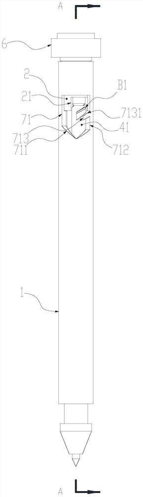
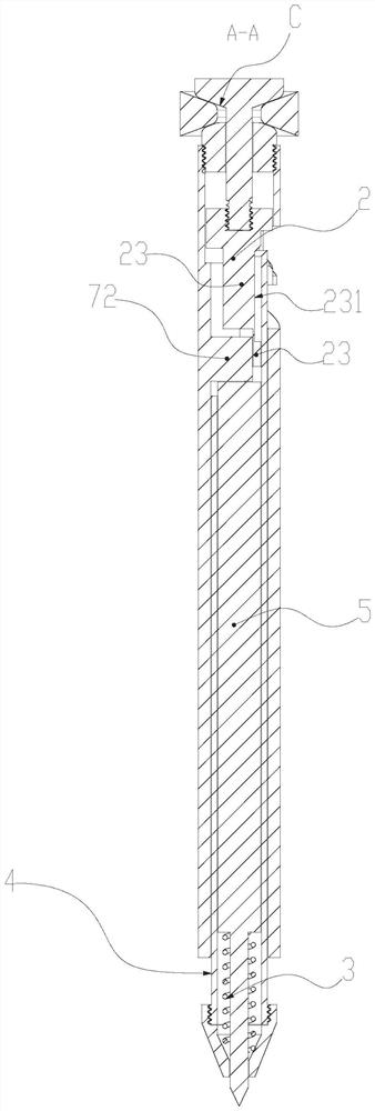
[0101] Such as Figures 1 to 2 A micro-trigger pen shown includes an outer rod 1, a reset member 3, a writing instrument body 5 and an adjustment module. The above adjustment module includes a control part 2 , an adjustment part 4 and a trigger assembly 6 .

[0102] A control rod 21 is arranged on the above-mentioned control member 2 .

[0103] The outer rod 1 is provided with a positioning slot 71 and a positioning portion 72 . The positioning groove 71 is provided with a core retracting switching wall 711 , a core retracting limiting wall 712 and a core exiting boss 713 . The core-out boss 713 is provided with a core-out sliding wall 7131 .

[0104] The adjustment member 4 is provided with a displacement member 41 , and the displacement member 41 moves in the positioning groove 71 .

[0105] The writing instrument main body 5 and the reset member 3 are placed in the adjustment member 4 , and the reset member 3 is specifically located between the writing instrument main b...

Embodiment 2

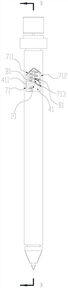
[0117] Such as Figures 3 to 4 A micro-trigger pen shown includes an outer rod 1, a reset member 3, a writing instrument body 5 and an adjustment module. The above adjustment module includes a control part 2 , an adjustment part 4 and a trigger assembly 6 .

[0118] A control rod 21 is arranged on the above-mentioned control member 2 .

[0119] The outer rod 1 is provided with a positioning groove 71 . The positioning groove 71 is provided with a core retracting switching wall 711 , a core retracting limiting wall 712 and a core exiting boss 713 . The core-out boss 713 is provided with a core-out sliding wall 7131 .

[0120] The adjustment member 4 is provided with a displacement member 41 , and the displacement member 41 moves in the positioning groove 71 .

[0121] The adjusting member 4 is also provided with an adjusting conflicting portion 42 and an adjusting pressing portion 43 . The above-mentioned writing instrument main body 5 and reset member 3 are placed inside ...

Embodiment 3

[0136] Such as Figures 5 to 9 A micro-trigger stylus is shown. It includes an outer rod 1, a reset member 3, a writing instrument main body 5 and an adjustment module. The above adjustment module includes a control part 2 , an adjustment part 4 , a trigger assembly 6 and a positioning part 7 .

[0137] A control rod 21 is arranged on the above-mentioned control member 2 .

[0138] Above-mentioned locating member 7 is installed in the outer bar 1, can not move up and down substantially, preferably do not move up and down. The above-mentioned positioning member 7 is provided with a positioning groove 71 . The positioning groove 71 is provided with a core retracting switching wall 711 , a core retracting limiting wall 712 and a core exiting boss 713 . The core-out boss 713 is provided with a core-out sliding wall 7131 .

[0139] The adjustment member 4 is provided with a displacement member 41 , and the displacement member 41 moves in the positioning groove 71 .

[0140] The...


PUM


Abstract

The invention relates to a pen, and particularly relates to a micro-trigger pen. The micro-trigger pen comprises an outer rod, a reset piece, a writing tool body and an adjusting module. The adjusting module comprises a control piece, an adjusting piece, a trigger assembly and a positioning piece. Core collecting and core discharging of the writing tool body can be controlled through the adjusting module. Meanwhile, through cooperation of the trigger assembly and the control piece, core releasing and collecting are conducted in a core pulling manner, the effect achieved in the manner is extremely good, the actually needed trigger force is extremely small, the brought trigger experience is extremely good, and real micro-trigger core collecting can be achieved. All structural assemblies are designed in a modular manner, production and assembling are simpler, cost is controllable, and micro-trigger core collecting can be achieved with the cost of a common pen. Structural coverage is comprehensive, and multiple trigger manners are achieved. The stability of the operation process is extremely good, operation is overall very smooth, the overall structural design is perfect, and meanwhile durability is achieved.

Description

technical field [0001] The invention relates to a pen, in particular to a micro-trigger pen. Background technique [0002] With the continuous development of the new era, more new technologies began to appear, including major upgrades for pens, such as: [0003] CN202011512192.6 A 360-degree trigger structure and a pen using the structure; this technology realizes the pen’s 360-degree trigger core retraction function, and achieves an excellent function similar to automatic core retraction. The effect of the method is excellent, and it can better reflect the rapid changes in the new era and the huge upgrade of the pen operation method, which greatly improves people's pen operation experience and achieves better intelligence with mechanical technology; however, the scheme adopts Although the joint bearing is the most stable and common structure for 360-degree rotating mechanisms in today's society, this mature technology is too expensive for the 360-degree trigger core retrac...

Claims


Application Information

Patent Timeline
Patent Type & Authority Applications(China)
IPC IPC(8): B43K24/02B43K24/03
CPCB43K24/02B43K24/03
Inventor 宋迎迎
Owner 杭州冰汽科技有限公司
Why Eureka
Try Eureka