Orthognathic surgery teaching mold and use method thereof
A surgical operation and mold technology, applied in the field of medical teaching, can solve the problems of high difficulty in surgery, long training cycle for talents, lack of surgical demonstration teaching molds, etc., to shorten the training period and improve the effect of deep understanding.
- Summary
- Abstract
- Description
- Claims
- Application Information
AI Technical Summary
Problems solved by technology
Method used
Image
Examples
Embodiment 1
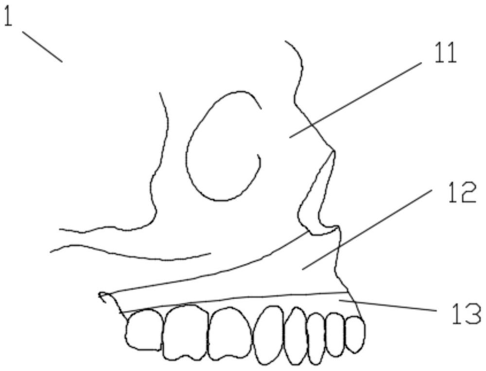
[0052] Such as Figure 1-Figure 11 As shown, a set of teaching molds for orthognathic surgery disclosed in this embodiment includes an upper jaw mold 1 and a lower jaw mold 2 .
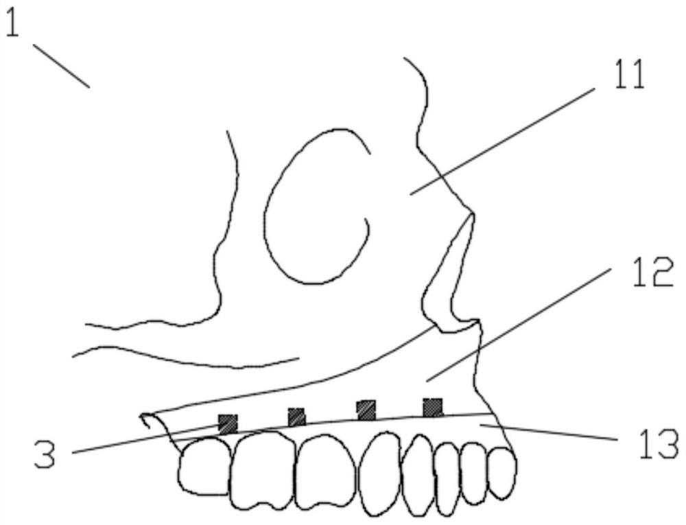
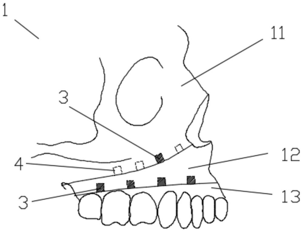
[0053] Such as Figure 1-Figure 3 As shown, the maxillary mold 1 includes a skull module 11 , a maxilla module 12 and an upper dentition module 13 .
[0054] The maxillary module 12 is located between the skull module 11 and the upper dentition module 13 , the upper side of the upper jaw module 12 is connected with the skull module 11 , and the upper side of the upper dentition module 13 is detachably connected with the upper jaw module 12 .
[0055] There are many detachable connection methods, such as threaded connection, adhesive bonding, etc., which can be selected by those skilled in the art according to needs. It is worth noting that this embodiment also provides two new detachable connection methods, as follows:
[0056] Mode 1, the maxillary module 12 is connected to the upper dentition mod...
Embodiment 2
[0081] In this embodiment, on the basis of Embodiment 1, the mandibular distal bone segment module 21 is divided into two parts, the mandibular distal bone segment main module 26 and the chin module 25, as Figure 12 shown.
[0082] The position of the chin module 25 can be adjusted front, back, left, and right relative to the main module 26 of the distal mandibular bone segment.
[0083] In particular, the chin module 25 is slidably connected with the main module 26 of the distal mandibular bone segment. Such as Figure 13 As shown, a cross-shaped chute 261 can be set at the position where the main module 26 of the distal mandibular bone segment is connected to the chin module 25. There is a suitable slider on the chin module 25, and the slider is installed in the cross-shaped chute. 261 in.
[0084] After the relative position of the chin module 25 and the mandible distal bone section main module 26 is adjusted in place, the chin module 25 and the mandible distal bone sec...
Embodiment 3
[0092] The difference of this embodiment in Embodiment 1 or Embodiment 2 is that: the left side and the right side of the mandibular distal bone segment module 21 are suitable for the right mandibular proximal bone segment module 22 and the left mandibular proximal bone segment module 23. The matching groove, the right mandibular near-cardiac segment module 22 and the left mandible near-cardiac segment module 23 are installed in the grooves, so that the right mandible near-cardiac segment module The surface of the module 22 , the proximal bone segment module 23 of the left mandible, and the distal bone segment module 21 of the mandible are flush. Optionally, the right mandibular proximal bone segment module 22 and the left mandibular proximal cardiac bone segment module 23 are divided into two parts, the front bone segment 231 and the rear bone segment 232, such as Figure 15 , Figure 16 shown.
[0093] A plurality of pin holes 4 or pins 3 are arranged along the front-back ...
PUM
 Abstract
Description
Claims
Application Information
 - R&D
- Intellectual Property
- Life Sciences
- Materials
- Tech Scout
- Unparalleled Data Quality
- Higher Quality Content
- 60% Fewer Hallucinations
Browse by: Latest US Patents, China's latest patents, Technical Efficacy Thesaurus, Application Domain, Technology Topic, Popular Technical Reports.
© 2025 PatSnap. All rights reserved.Legal|Privacy policy|Modern Slavery Act Transparency Statement|Sitemap|About US| Contact US: help@patsnap.com


