
Emergency communication equipment mounting structure

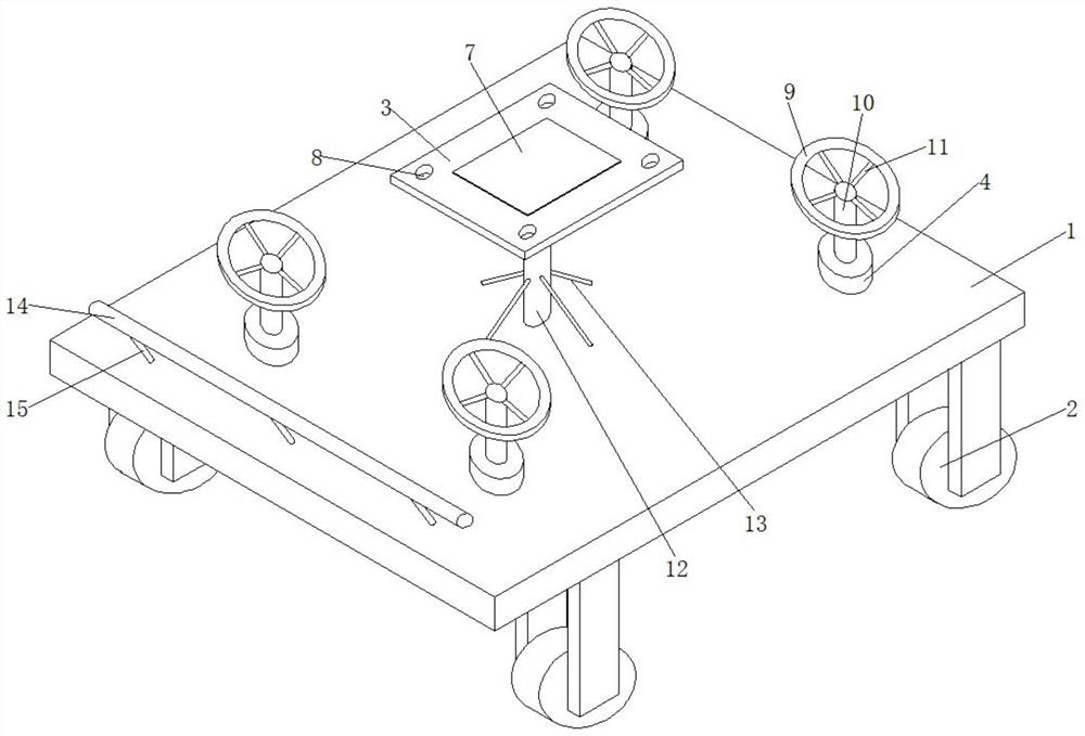
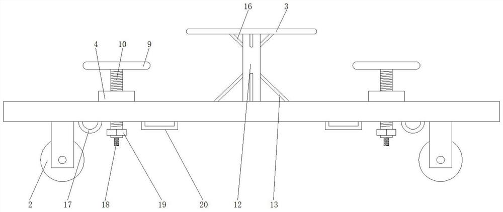
An installation structure and emergency communication technology, applied in emergency/dangerous communication services, selection devices, electrical components, etc., can solve the problem of poor stability and locking of emergency communication equipment, failure of devices to be delivered to the place of use, and communication equipment that cannot be carried to the place Need to use the position and other issues to achieve the effect of avoiding the structure falling off

Inactive Publication Date: 2022-02-08
徐州独角兽信息科技有限公司
View PDF0 Cites 0 Cited by
  • Summary
  • Abstract
  • Description
  • Claims
  • Application Information

AI Technical Summary

Problems solved by technology

[0003] Emergency communication equipment needs to be installed above the bracket, so that the communication vehicle can transfer the equipment to the required location. However, in actual use, disasters in some remote areas, such as mudslides and other disasters that occur in mountainous areas, ordinary communication vehicles Unable to carry the communication equipment to the required location, resulting in the failure of the device to be delivered to the usage location, and the stable locking effect on the emergency communication equipment is not good

Method used


Image

  • Emergency communication equipment mounting structure
  • Emergency communication equipment mounting structure
  • Emergency communication equipment mounting structure

Examples


Embodiment Construction

[0028] In order to make the technical means, creative features, goals and effects achieved by the present invention easy to understand, the present invention will be further described below in conjunction with specific embodiments.

[0029] In describing the present invention, it should be understood that the terms "upper", "lower", "front", "rear", "left", "right", "top", "bottom", "inner", " The orientation or positional relationship indicated by "outside", etc. is based on the orientation or positional relationship shown in the drawings, and is only for the convenience of describing the present invention and simplifying the description, rather than indicating or implying that the referred device or element must have a specific orientation, so as to Specific orientation configurations and operations, therefore, are not to be construed as limitations on the invention.

[0030] In the description of the present invention, it should be noted that, unless otherwise specified and...


PUM


Abstract

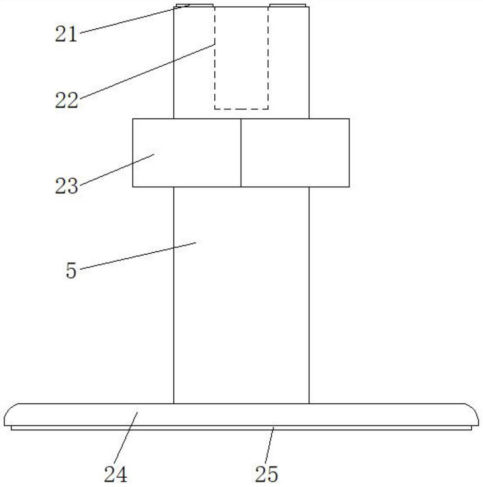
The invention relates to the technical field of communication equipment, and discloses an emergency communication equipment mounting structure which comprises a base, rubber wheels, a mounting plate, a screw block, a first supporting rod and a second supporting rod. The number of the rubber wheels is four, the four rubber wheels are installed at the four corners of the lower portion of the base, the mounting plate is transversely arranged on the upper surface of the base, the mounting plate is located in the middle of the surface of the base, the mounting plate is parallel to the base, and the mounting plate is supported and fixed to the upper portion of the base through the supporting columns. The mounting plate is arranged above the middle of the base, emergency communication equipment can be mounted on the mounting plate, four rubber wheels are mounted at the four corners of the lower portion of the base, a lead screw with a connecting structure is arranged, and the bottom of the lead screw can be connected with a first supporting rod or a second supporting rod in a replaceable mode; the base can be conveniently fixed in a carriage of a tractor or on the top of an off-road vehicle through a bottom structure of the device, the device can be placed on the soil ground to be stably fixed, and the device can be conveniently conveyed to a mountainous area to be stably fixed and used.

Description

technical field [0001] The invention relates to the technical field of communication equipment, in particular to an installation structure of emergency communication equipment. Background technique [0002] At present, communication equipment is a general term for communication equipment set up in a certain area to transmit radio wave information. It is mainly divided into wired communication equipment and wireless communication equipment. , Industrial Ethernet communication and conversion equipment between various communication protocols, in the event of natural or man-made sudden disasters, it is necessary to use emergency communication equipment to restore normal communication in the disaster-stricken area. [0003] Emergency communication equipment needs to be installed above the bracket, so that the communication vehicle can transfer the equipment to the required location. However, in actual use, disasters in some remote areas, such as mudslides and other disasters that...

Claims


Application Information

Patent Timeline
Patent Type & Authority Applications(China)
IPC IPC(8): H04W4/90H04Q1/02H04Q1/04
CPCH04W4/90H04Q1/02H04Q1/04
Inventor 傅宝山
Owner 徐州独角兽信息科技有限公司
Learn More