Multifunctional motor base

A motor base and multi-functional technology, applied in the direction of electrical components, electromechanical devices, electric components, etc., can solve problems such as unfavorable installation and disassembly, inability to adjust the output direction of the motor according to demand, and troubles in use

Pending Publication Date: 2022-02-11
泰信电机(苏州)有限公司
View PDF0 Cites 0 Cited by
  • Summary
  • Abstract
  • Description
  • Claims
  • Application Information

AI Technical Summary

Problems solved by technology

At present, there is also a suspended motor on the market, which is used for high-altitude operations and movable transmissions. The motor is usually fixed in the motor base when in use; while the traditional motor base h

Method used


Image

  • Multifunctional motor base
  • Multifunctional motor base

Examples


Embodiment Construction

[0017] The present invention is described in further detail now in conjunction with accompanying drawing. The accompanying drawings are simplified schematic diagrams, which only illustrate the basic structure of the present invention in a schematic manner, so that they only show the components relevant to the present invention.

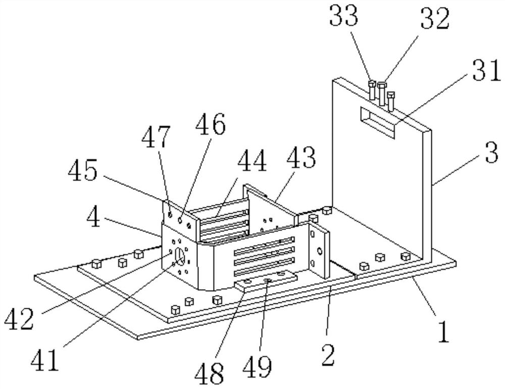
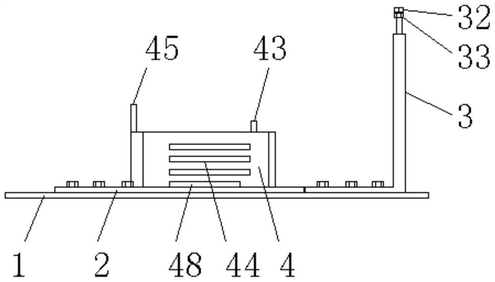
[0018] Please refer to Figure 1-2 , a multifunctional motor base, comprising a base 1 and a movable plate 2 fixed on the base 1 and an L-shaped fixed plate 3, the movable plate 2 and the L-shaped fixed plate 3 are hinged through a hinge, and the movable plate 2 is A motor base 4 is provided, and the motor is arranged in the motor base 4. The two sides of the motor base 4 are respectively provided with cooling grooves 44, and one end of the motor base 4 is provided with a shaft hole 41, and the shaft hole 41 Fixing holes 42 are respectively provided around, the other end of the motor base 4 is provided with a limit fixing plate 43, and the motor base...


PUM


Abstract

The invention discloses a multifunctional motor base. The motor base comprises a base, and a movable plate and an L-shaped fixed plate which are fixed on the base. The movable plate and the L-shaped fixed plate are hinged through a hinge, a motor base is arranged on the movable plate, a motor is arranged in the motor base, two sides of the motor base are respectively provided with a heat dissipation groove, one end of the motor base is provided with a shaft hole, fixing holes are formed in the periphery of the shaft hole, a limiting fixing plate is arranged at the other end of the motor base, a locking plate is arranged at the position, above one side of the shaft hole, of the motor base, and when the motor base rotates by 90 degrees to be perpendicular to the base, the locking plate is matched with a locking mechanism on an L-shaped fixing plate. The use state of the novel multifunctional motor base can be adjusted according to requirements, the internal motor can be horizontally or vertically arranged, the transmission direction can be conveniently changed, and the novel multifunctional motor base is stable in overall structure, convenient to mount and dismount and suitable for application and popularization.

Description

technical field [0001] The invention relates to the technical field of motors, in particular to a multifunctional motor base. Background technique [0002] The motor refers to an electromagnetic device that realizes the conversion or transmission of electric energy according to the law of electromagnetic induction. Its main function is to generate driving torque and provide power for various machinery or electrical appliances. Its types are also diverse, such as synchronous motors, asynchronous motors, DC motor etc. At present, there is also a suspended motor on the market, which is used for high-altitude operations and movable transmissions. The motor is usually fixed in the motor base when in use; while the traditional motor base has a single structure and cannot adjust the motor according to demand. The output direction, and the whole is mostly integrated, which is not conducive to installation and disassembly, and brings troubles to people's use. Contents of the inven...

Claims


Application Information

Patent Timeline
IPC IPC(8): H02K5/26H02K5/00
CPCH02K5/26H02K5/00
Inventor 崔光镐
Owner 泰信电机(苏州)有限公司
Why Eureka
Try Eureka