
Manual and electric switching device and electric actuator

A switching device, hand-operated technology, applied in valve devices, mechanical drive clutches, valve operation/release devices, etc., can solve the problems of not easy operation, injury to operators, inability to automatically switch, etc., and achieve reliable self-locking characteristics Effect

Pending Publication Date: 2022-02-18
常州电站辅机股份有限公司
View PDF5 Cites 0 Cited by
  • Summary
  • Abstract
  • Description
  • Claims
  • Application Information

AI Technical Summary

Problems solved by technology

[0003] At present, most of the hand and electric switching devices of electric actuators on the market are too simple, and there are potential safety hazards in operation. When switching from electric state to manual state, rely on the micro switch to control the start and stop of the motor
If the electrical components are used for a long time to cause aging and failure, the motor will drive the manual parts to rotate, which will injure the operator
When electric operation is required, it is necessary to manually exit the manual state, and it cannot be switched automatically, and the operation is not easy enough

Method used


Image

  • Manual and electric switching device and electric actuator
  • Manual and electric switching device and electric actuator
  • Manual and electric switching device and electric actuator

Examples


Embodiment 1

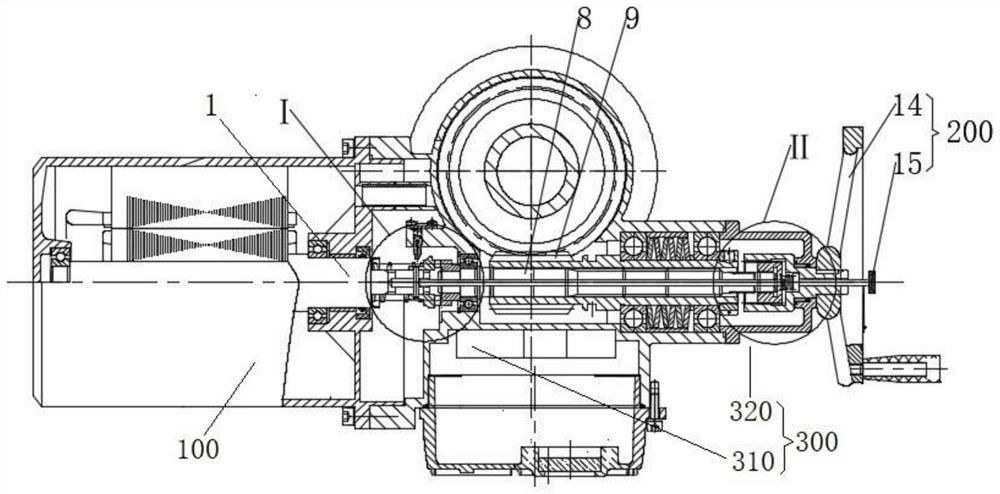
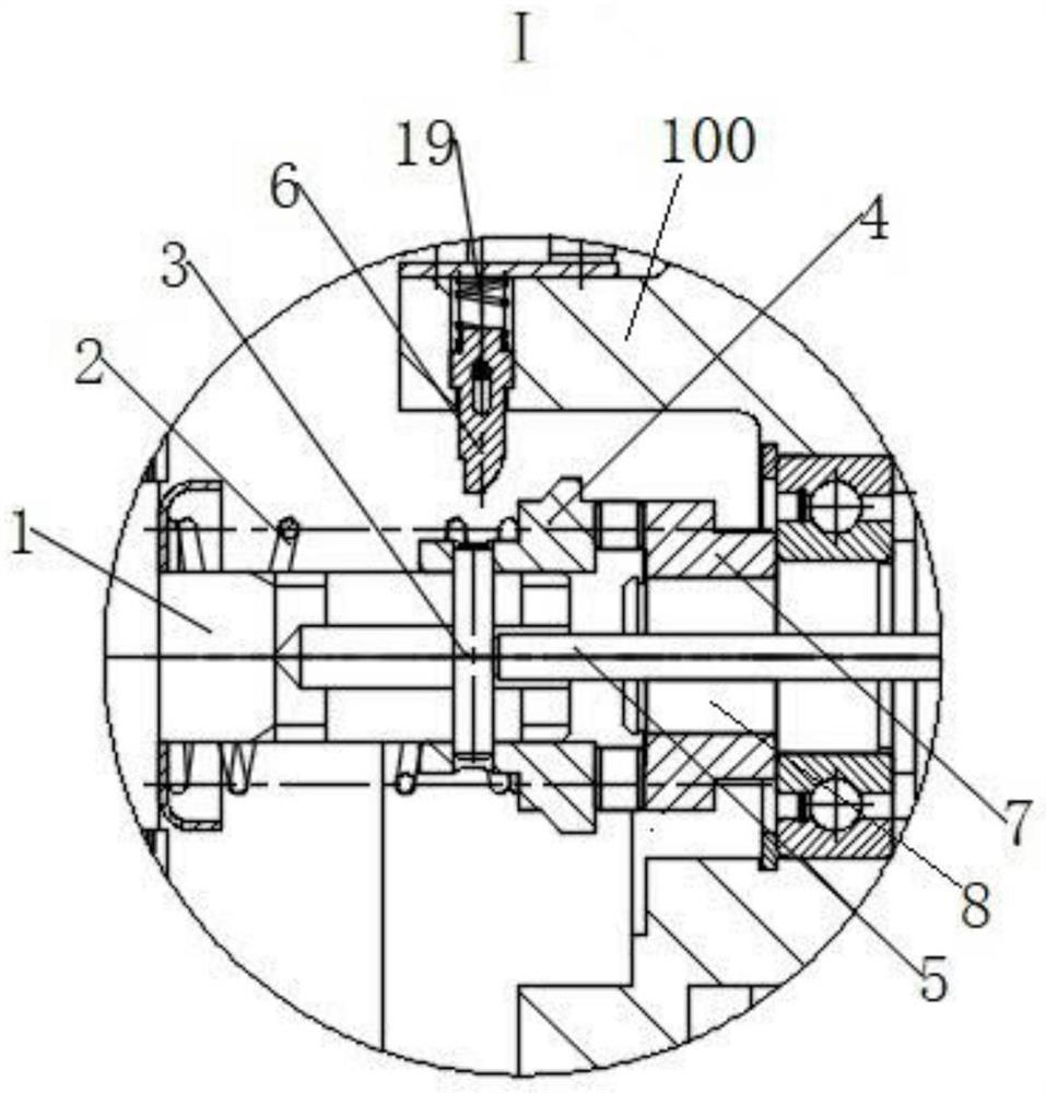
[0036] see figure 1, the present invention provides a manual electric switching device, including a housing 100 , a first motor 1 , a manual drive assembly 200 and a clutch assembly 300 . The clutch assembly 300 is installed in the housing 100 , the first motor 1 is installed at one end of the clutch assembly 300 , and the manual drive assembly 200 is installed at the other end of the clutch assembly 300 . The first motor 1 and the manual drive assembly 200 can be connected with the clutch assembly 300 respectively: when the clutch assembly 300 is connected to the manual drive assembly 200 and disconnected from the first motor 1, the The torque of the manual drive assembly 200 can be transmitted to the clutch assembly 300; when the clutch assembly 300 is connected to the first motor 1 and disconnected from the manual drive assembly 200, the first motor 1 Torque can be transmitted to the clutch assembly 300, and the manual drive assembly 200 is a detachable structure.

[0037...

Embodiment 2

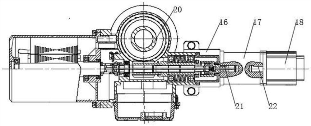
[0054] see figure 2 , this embodiment provides a manual electric switching device. This embodiment is an improvement made on the technical basis of the first embodiment above. key 21 and a second key 22. The fixed frame 16 is installed on the outside of the spline sleeve 11, and the second motor 18 is installed on the inside of the fixed frame 16 corresponding to the outer end of the push rod 13. Between the second motor 18 and the push rod 13 The planetary reducer 17 is installed, the first key 21 is installed between the planetary reducer 17 and the handwheel claw 10, the planetary reducer 17 and the second motor 18 are installed between the Second key 22.

[0055] In this embodiment, the second motor 18 and the planetary reducer 17 can replace the hand wheel 14 . When the device needs to be switched from the electric state to the manual state, the handle 15 is first pressed to move the push rod 13 into the device, and then the planetary reducer 17 and the second motor ...

Embodiment 3

[0058] read on Figure 1 to Figure 4 , this embodiment also provides an electric actuator, including the manual electric switching device described in Embodiment 1 and Embodiment 2 and an output component 20 , the output component 20 is engaged with the worm 9 .


PUM


Abstract

The invention provides a manual and electric switching device and an electric actuator. The manual and electric switching device comprises a shell, a first motor, a manual driving assembly and a clutch assembly; the clutch assembly is mounted in the shell, the first motor is mounted at one end of the clutch assembly, the manual driving assembly is mounted at the other end of the clutch assembly, a limiting shaft is mounted in the shell, one end of the limiting shaft can be connected with the clutch assembly in a matched mode, the other end of the limiting shaft is connected with a third compressed spring, the third compressed spring is connected with the inner wall of the shell, and the limiting shaft is used for controlling the meshing relation between the clutch assembly and the first motor. When the clutch assembly is switched to the manual state, the clutch assembly is completely disconnected with the first motor, and a reliable self-locking characteristic is achieved; and when operation is needed in the electric state, after the first motor is started, the manual mode loses efficacy due to high-speed rotation of the first motor, then the clutch assembly automatically recovers to the electric state, and manual switching operation is not needed.

Description

technical field [0001] The invention relates to the field of electric actuators, in particular to a manual electric switching device and an electric actuator. Background technique [0002] The electric actuator, a commonly used mechatronics equipment in the field of automation control, is the execution terminal in the automatic intelligent adjustment system (detection equipment, adjustment equipment, execution equipment and adjustment object) of the industrial production process. The electric actuator is mainly driven by a motor, and is output to the output part to drive the valve through gears, worm gears and other deceleration parts. When the drive power is lost on site, or the valve needs to be opened and closed in an emergency, the switch can only be realized through the mechanical part of the electric actuator, which is usually called a manual electric switching device. [0003] At present, most of the hand and electric switching devices of electric actuators on the ma...

Claims


Application Information

Patent Timeline
Patent Type & Authority Applications(China)
IPC IPC(8): F16K31/05F16K31/53F16K31/60F16D11/14
CPCF16K31/05F16K31/047F16K31/53F16K31/60F16D11/14F16D2011/004F16D2011/008
Inventor 邵杰许伟伟曹超刘亚男
Owner 常州电站辅机股份有限公司
Learn More