Pixel-based curved surface near-to-eye display method, displayer and display system

A near-eye display and near-eye display technology, which is applied to static indicators, instruments, optics, etc., can solve the problems of natural scene disorder, light transmittance drop, interference, etc., and achieve the effect of large visual space and good AR effect

Pending Publication Date: 2022-02-18
JIANGSU LIJUN INTELLIGENT TECH CO LTD
View PDF1 Cites 0 Cited by
  • Summary
  • Abstract
  • Description
  • Claims
  • Application Information

AI Technical Summary

Problems solved by technology

Simply put, this refraction structure is essentially an optical waveguide structure, which is no different from the optical waveguide in the principle of imaging light output. When applied to products similar to AR glasses, the refraction structure will interfere with half of the natural light and make half The angle of natural light is deflected, which means that if you want to avoid the deflection of natural light, you can only use a normally black screen structure, which will inevitably cause a decrease in light transmittance. disorder

Method used


Image

  • Pixel-based curved surface near-to-eye display method, displayer and display system
  • Pixel-based curved surface near-to-eye display method, displayer and display system
  • Pixel-based curved surface near-to-eye display method, displayer and display system

Examples


Embodiment 1

[0071] combine Figure 3 to Figure 6 , to describe Embodiment 1 of the present invention in detail, but does not limit the claims of the present invention in any way.

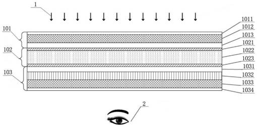
[0072] Therefore, a curved near-eye display method based on liquid crystal pixels is designed, using several transmissive LCD units 11 to form a liquid crystal curved panel 12, using natural light 1 as the light source of each LCD unit 11, so that the liquid crystal pixels of all LCD units 11 emit light 16 to Focusing on the same focal point, the focal point 18 is located on the vertical center line of the liquid crystal curved panel 12 and falls in the user's eyeball 2 .

[0073] Such as image 3 As shown, it is a specific application of the above technical solution. In this application, the liquid crystal curved panel 12 is designed as a concave spherical surface, and the LCD unit located in the center of the liquid crystal curved panel 12 is defined as the origin LCD unit 13, and the plane where the origin ...

Embodiment 2

[0101] combine Figure 7 to Figure 13 , to describe Embodiment 2 of the present invention in detail, but does not limit the claims of the present invention in any way.

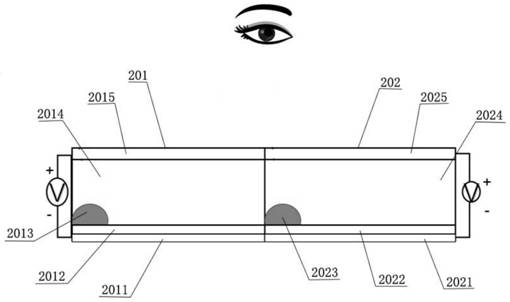
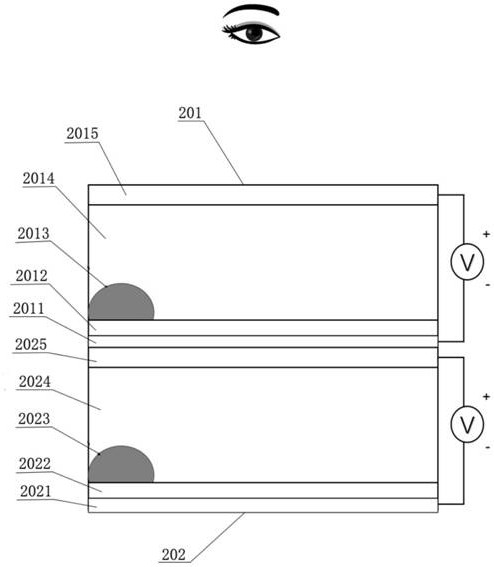
[0102] A curved surface near-eye display method based on oil film pixels, using several transmissive EW units 21 to form an electrowetting curved surface panel 22, using natural light 1 as the light source of each EW unit 21, so that the oil film pixels of all EW units 21 reflect light 26 to the same direction The focal point 28 is focused on the vertical centerline of the electrowetting curved panel 22 and falls within the user's eyeball 2 .

[0103] Such as Figure 7 As shown, it is a specific application of the above technical solution. In this application, the electrowetting curved panel 22 is designed as a concave spherical surface, and the EW unit located in the center of the electrowetting curved panel 22 is defined as the origin EW unit 23, and the origin EW unit 23 The plane where it is located is d...


PUM

PropertyMeasurementUnit
transmittivityaaaaaaaaaa

Abstract

The invention relates to the technical field of near-to-eye display, and in particular, relates to a pixel-based curved surface near-to-eye display method, a displayer and a display system. A plurality of transmission type LCD units or reflection type EW units are utilized to form a curved surface panel, and natural light is adopted as a light source of the LCD units or the EW units; and liquid crystal pixel emergent light rays of all the LCD units or oil film pixel reflected light rays of the EW units are focused to the same focus point, and the focus point is located on the vertical center line of the curved surface panel and falls into eyeballs of a user. According to the invention, only the distance between the focal length and the curved surface during imaging of the curved surface pixel is changed, so that an ideal mode for enlarging the field angle in near-to-eye display is provided; and meanwhile, the natural light transmission of the transparent curved surface is not changed when the emergent ray angle or the reflected ray angle during imaging of the pixel is changed; therefore, co-existence of virtual information and reality information is guaranteed, and a good AR effect is achieved.

Description

technical field [0001] The invention relates to the technical field of near-eye display, in particular to a pixel-based curved near-eye display method, display and display system. Background technique [0002] Augmented reality (Augmented Reality, referred to as AR) technology is a technology that ingeniously integrates virtual information with the real world. Computer-generated text, images, 3D models, music, video and other virtual information are simulated and applied to the real world. The two kinds of information complement each other, thereby realizing the "enhancement" of the real world. [0003] Since the beginning of the 20th century, with the development of AR technology, more and more well-known electronics manufacturers have devoted themselves to the research of AR products. For example, Google in the United States and Epson in Japan have successively launched their own smart glasses products. [0004] As shown in Table 1, the optical display systems used in exi...

Claims


Application Information

Patent Timeline
Patent Type & Authority Applications(China)
IPC IPC(8): G02B27/01G02F1/1333G02F1/13357G09G3/34G02B26/00
CPCG02B27/0101G02F1/1333G02F1/133602G09G3/348G02B26/005
Inventor 汪勇汪越天
Owner JIANGSU LIJUN INTELLIGENT TECH CO LTD
Why Eureka
Try Eureka