
Chain tensioning mechanism

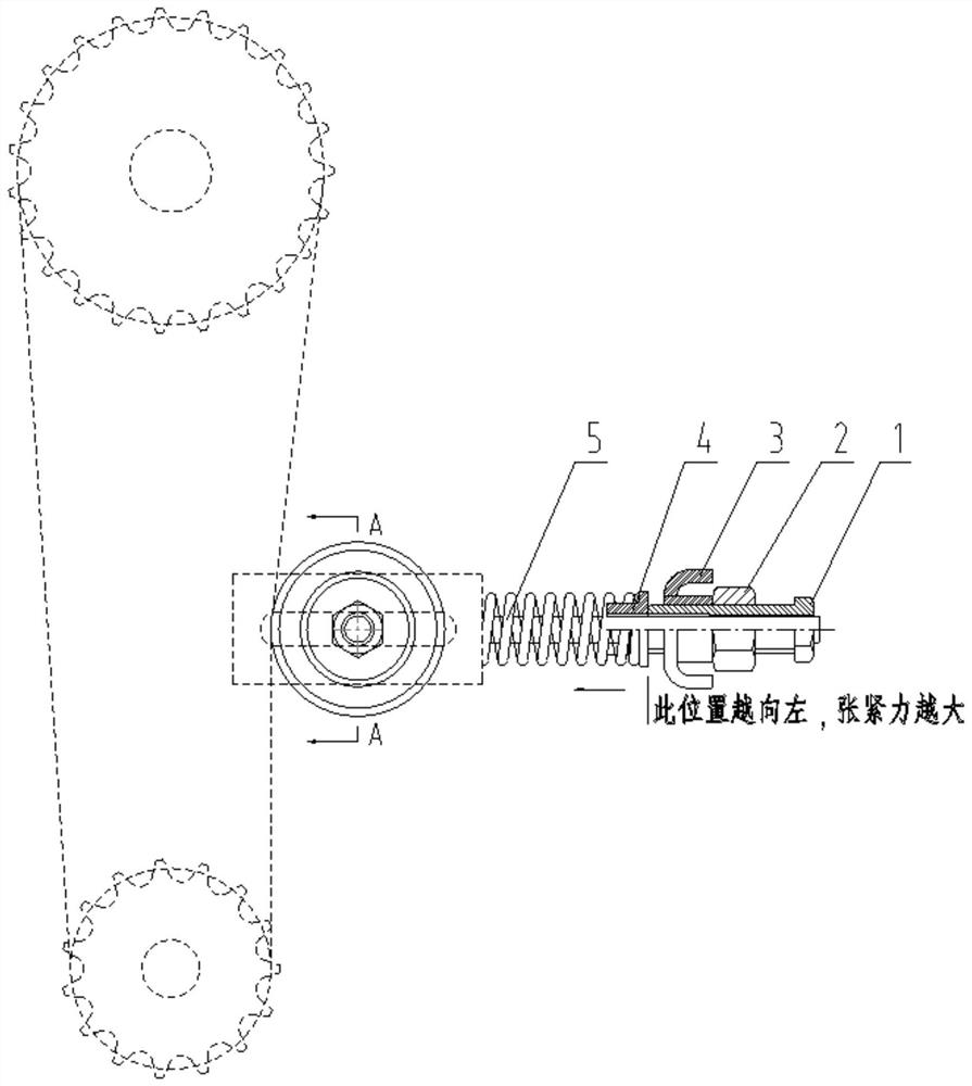
A tensioning mechanism and chain technology, applied in belts/chains/gears, mechanical equipment, transmission devices, etc., can solve problems such as poor sprocket support rigidity, sprocket end face runout, and difficulty in adjusting the coplanarity of sprockets. The effect of improving the stiffness of the support and reducing the jump

Pending Publication Date: 2021-06-29
江苏沃得高新农业装备有限公司
View PDF0 Cites 0 Cited by
  • Summary
  • Abstract
  • Description
  • Claims
  • Application Information

AI Technical Summary

Problems solved by technology

[0003] The structure of the tensioner is various, which generally includes a fixed structure and an elastic automatic adjustment structure. Automatic rebound controls the tension of the belt and chain. At present, the chain tensioner that can be automatically adjusted in China mostly uses a spring structure, but the spring-type tensioning mechanism has the following problems. First, it is difficult to adjust the coplanarity with the sprocket Second, the end surface of the sprocket has a serious beating, and third, the support rigidity of the sprocket is poor; therefore, a chain tensioning mechanism is urgently needed to solve the above problems

Method used


Image

  • Chain tensioning mechanism
  • Chain tensioning mechanism
  • Chain tensioning mechanism

Examples


Embodiment Construction

[0024] The present invention is described in further detail now in conjunction with accompanying drawing. In the description of the present application, it should be understood that the orientations or positional relationships indicated by the terms "left side", "right side", "upper", "lower" are based on the orientations or positional relationships shown in the drawings, and are only For the purpose of describing the present invention and simplifying the description, rather than indicating or implying that the device or element referred to must have a specific orientation, be constructed and operate in a specific orientation, "first", "second" and the like do not represent components importance, and therefore should not be construed as limiting the invention. The specific dimensions used in this embodiment are only for illustrating the technical solution, and do not limit the protection scope of the present invention.

[0025] In order to solve the defects of the tensioning ...


PUM


Abstract

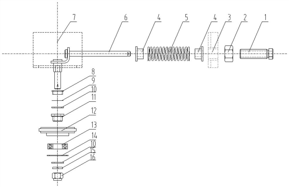
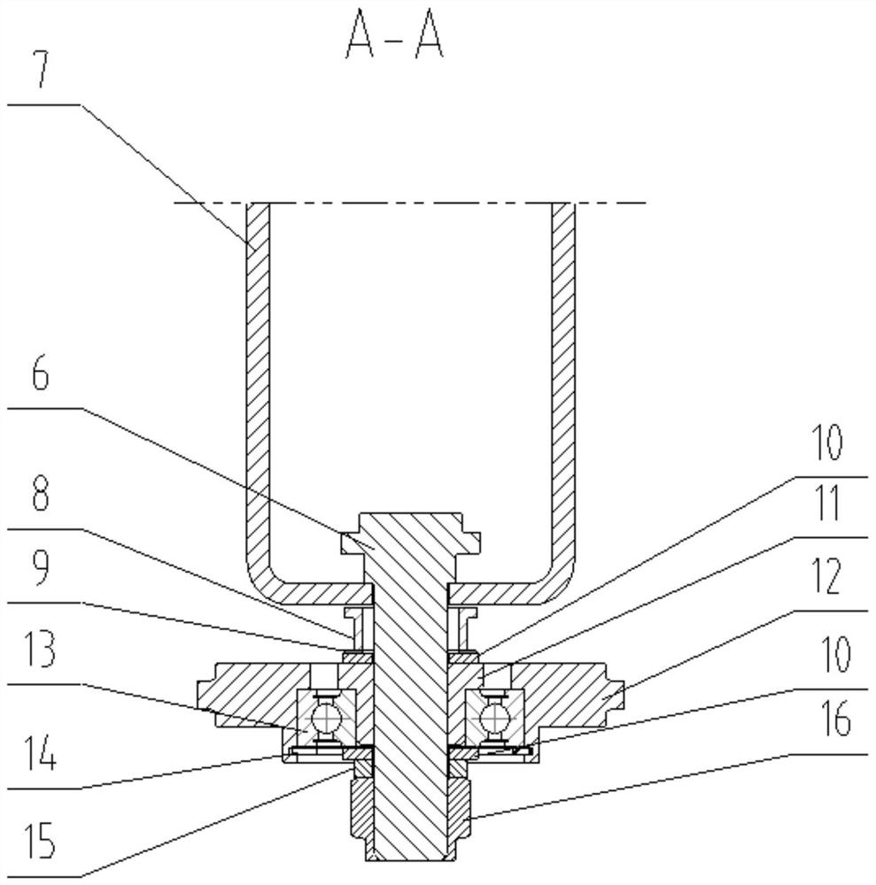
The invention relates to a chain tensioning mechanism. The chain tensioning mechanism comprises a U-shaped plate fixed to a side plate, a long-strip-shaped hole is formed in the closed end of the U-shaped plate, a square neck screw is in an L shape, the A end of the square neck screw penetrates through an opening of the U-shaped plate and stretches out of the long-strip-shaped hole in the closed end of the U-shaped plate, and the B end of the square neck screw stretches out of a space formed by two perpendicular parts of the U-shaped plate; and an adjusting device used for adjusting the end face position of a tensioning wheel is installed at the end A of the square neck screw, the end face of the tensioning wheel and the end face of a chain wheel are located on a same plane, and a pressure adjusting device used for adjusting the tensioning force of the tensioning wheel is installed at the end B of the square neck screw. The problems generated in the background technology are solved, and the service life of a chain is prolonged.

Description

technical field [0001] The invention relates to a chain tensioning mechanism, which belongs to the field of tensioners. Background technique [0002] The tensioner is a commonly used holding device on the belt and chain transmission system. Its characteristic is to keep the belt and chain with proper tension during the transmission process, so as to avoid the belt slipping, or to prevent the synchronous belt from skipping teeth or detaching the teeth. drag out. Or prevent the chain from loosening and falling off, and reduce the wear and tear of sprockets and chains. [0003] The structure of the tensioner is various, which generally includes a fixed structure and an elastic automatic adjustment structure. Automatic rebound controls the tension of the belt and chain. At present, the chain tensioner that can be automatically adjusted in China mostly uses a spring structure, but the spring-type tensioning mechanism has the following problems. First, it is difficult to adjust ...

Claims


Application Information

Patent Timeline
Patent Type & Authority Applications(China)
IPC IPC(8): F16H7/08
CPCF16H7/08F16H2007/0802F16H2007/0891F16H2007/0897
Inventor 偶宇君戴明
Owner 江苏沃得高新农业装备有限公司
Learn More