Carbon brush structure of collecting ring

A collector ring and carbon brush technology, applied in the field of collector rings, can solve problems such as current instability, discharge, and material waste

Active Publication Date: 2011-05-25
TAIWAN LONG HAWN ENTERPRISES
View PDF0 Cites 12 Cited by
  • Summary
  • Abstract
  • Description
  • Claims
  • Application Information

AI Technical Summary

Problems solved by technology

In this state, push the carbon brush 58 to make it press against the positive component force Fy of the surface of the conductive ring 62, and increase the tangential component force Fx, which will cause the carbon brush to jump when the conductive ring 62 rotates
When the carbon brush 58 jumps, the unfavorable si

Method used


Image

  • Carbon brush structure of collecting ring
  • Carbon brush structure of collecting ring
  • Carbon brush structure of collecting ring

Examples


Embodiment Construction

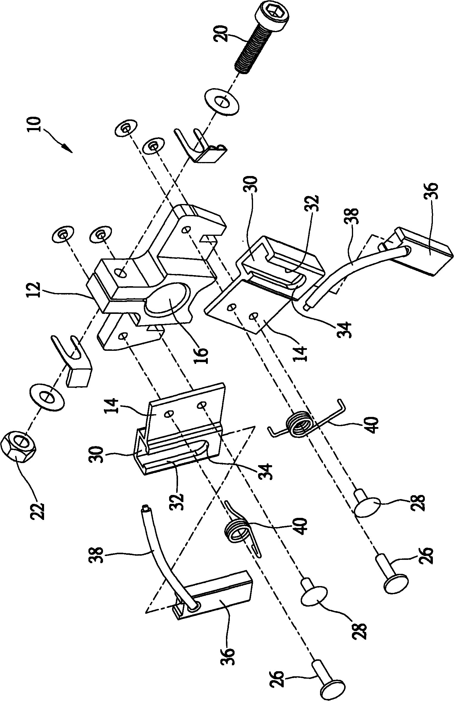
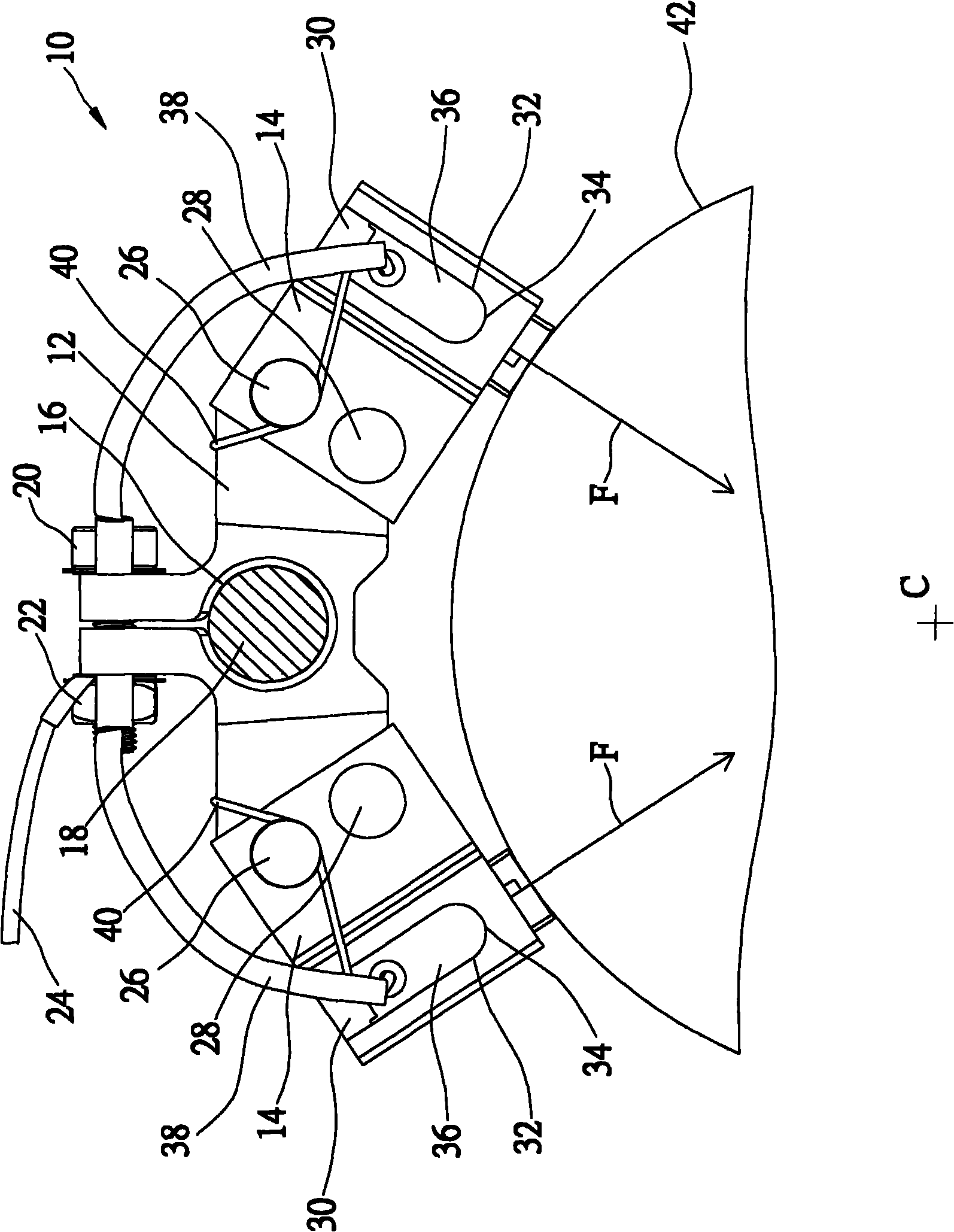
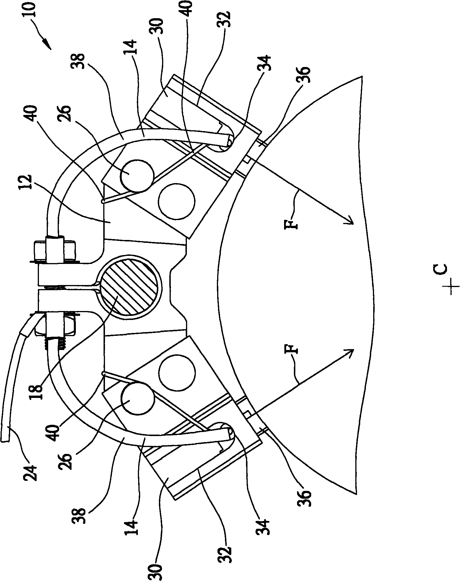
[0030] see figure 1 and figure 2 As shown, the carbon brush structure of the slip ring provided by a preferred embodiment of the present invention is mainly composed of a base 10 , two carbon brushes 36 and two biasing members.

[0031] The base 10 has a base 12 and two brackets 14 . The base 12 has a shaft hole 16 for passing through a rod 18 , and a bolt 20 and a nut 22 are used to fix the base 12 to a predetermined position of the slip ring. The bolt 20 and nut 22 hold a wire 24 for connection to an external circuit (not shown). The two brackets 14 are fixed on two sides of the base 12 by two rivets 26 and 28 respectively, and are skewed at a predetermined angle. Each bracket 14 has a guide rail 30 at its outer end. In this embodiment, the guide rail 30 is a rectangular pipe with open ends, and a guide groove 32 is defined on the side wall of the pipe 30 . The guide groove 32 starts from the outer end of the pipe 30 and extends inward about 3 / 4 of the length of the p...


PUM


Abstract

The invention discloses a carbon brush structure of a collecting ring. The carbon brush structure comprises a base, two carbon brushes and two bias voltage pieces, wherein the base is provided with two guide rails; the two carbon brushes are arranged on the guide rails of the base respectively and can move along the guide rails; the two bias voltage pieces act on the two carbon brushes respectively, drive the two carbon brushes to move towards a conducting ring of the collecting ring and keep the two carbon brushes in contact with the conducting ring. The two guide rails pass through the circle center of the conducting ring, so that the carbon brushes are prevented from jumping and are worn uniformly.

Description

technical field [0001] The present invention relates to a collector ring, and more specifically refers to a carbon brush structure of a collector ring. Background technique [0002] The existing collector ring mainly has a rotatable mandrel, on which there are conductive rings and insulating rings, and a number of carbon brush modules, which surround the conductive rings and are electrically connected to the conductive rings. status. Power can be conducted to the rotating conductive ring through the carbon brush module. [0003] Figure 4 Show a kind of existing carbon brush module 50, it has a base 52, is fixed on a pole 54, two swing arms 56, pivotally connected to the two ends of this base 52, two carbon brushes 58, are respectively fixed on The inner side of the two swing arms 56 and a spring 60 are connected to the two swing arms 56 at both ends. Through the action of the spring 60 , the two carbon brushes 58 can be kept in contact with the conductive ring 62 . [0...

Claims


Application Information

Patent Timeline
IPC IPC(8): H01R39/18H01R39/64
Inventor 游孟萩廖树城
Owner TAIWAN LONG HAWN ENTERPRISES
Why Eureka
Try Eureka