Guide rail machining device

A technology of guide rail processing and transverse guide rail, which is applied in the direction of manufacturing tools and other manufacturing equipment/tools, etc. It can solve the problems of difficult to guarantee the accuracy of workpieces, drilling accuracy and position size errors, and no roller support, so as to ensure the movement speed and Stability and precision of movement, improvement of rigidity and strength, and effect of preventing sagging deformation

Active Publication Date: 2015-09-23
LISHUI UNIV
View PDF9 Cites 13 Cited by
  • Summary
  • Abstract
  • Description
  • Claims
  • Application Information

AI Technical Summary

Problems solved by technology

[0002] At present, the guide rail drilling process has low production efficiency and low precision, which makes the product quality poor. For example, there are generally two drilling methods: method 1. The worktable is moved and the workpiece is installed on the workbench. This mechanism requires the length of the workbench. It is longer than the length of the workpiece, and the length of the lathe is required to be longer, at least twice that of the workbench. Therefore, after the size of the bed and workbench is increased, the cost will increase, the processing difficulty will increase, and the accuracy of the workpiece will not be guaranteed; Method 2: Fix the workpiece and move the tool spindle for processing the hole, so that the size of the mechanism is reduced. However, because the tool spindle is moving, the structural rigidity of the machine tool is relatively high. Increasing the rigidity will inevitably increase the specification of the guide rail to achieve it. In this way Increased cost of equipment
[0003] Moreover, in the processing process, a single workpiece is processed step by step. Specifically, to drill a workpiece, it is necessary to drill positioning holes, drill holes, ream holes, and chamfer both ends of the hole. Each process is processed by different processing equipment; this requires repeated positioning of the workpiece, low processing accuracy, and high labor intensity; the entire drilling process of the guide rail has low production efficiency and low processing accuracy.
In order to meet market demand, manufacturers are required to increase investment in machinery and personnel, resulting in high production costs.
[0004] When drilling and processing the guide rail, due to the long length of the guide rail, some of the longer guide rails reach more than 5 meters, and there is a row of mounting holes on the guide rail. Compression, if only a single cylinder presses the guide rail, the guide rail will be upturned, especially when the guide rail is first processed, or when the guide rail is processed in the last few steps, the guide rail does not fully enter the fixed clamping area of ​​the workbench , so that the position of the guide rail is shifted, and the fixation of the guide rail is not firm enough
[0005] Due to the long length of the guide rail, some longer guide rails reach more than 5 meters, there is generally a row of roller support at the feeding end of the guide rail, and a pull rod is pulled outward at the sending end of the guide rail, so there is no roller support at the sending end , which will easily lead to the sagging and bending of the guide rail, resulting in inaccurate control of the moving size and length of the workpiece
The guide rail requires a corresponding length of screw to pull the guide rail. Because the length of the screw is too long, the middle area of ​​the screw will sag, causing the screw to shake when it rotates, and the table can only move at a lower speed.
At the same time, after long-term use, the screw rod is deformed, resulting in low movement speed and poor precision.
[0006] Moreover, in the drilling device, it is generally driven by a motor, and the drill bit is installed on the rotating bearing seat through a fixture, and the fixture is connected to the output shaft of the motor through a fixed shaft, a coupling, or connected by a pulley. It is more complicated and takes up a lot of space, resulting in a larger overall volume of the machine
[0007] Therefore, in the process of guide rail processing, there are many problems in the prior art, which lead to high cost and bulky processing equipment, low machining accuracy of long guide rails, and relatively short guide rails, the errors of drilling accuracy and position size will increase. Big

Method used


Image

  • Guide rail machining device
  • Guide rail machining device
  • Guide rail machining device

Examples


Embodiment Construction

[0037] The present invention will be further described below in conjunction with accompanying drawing:

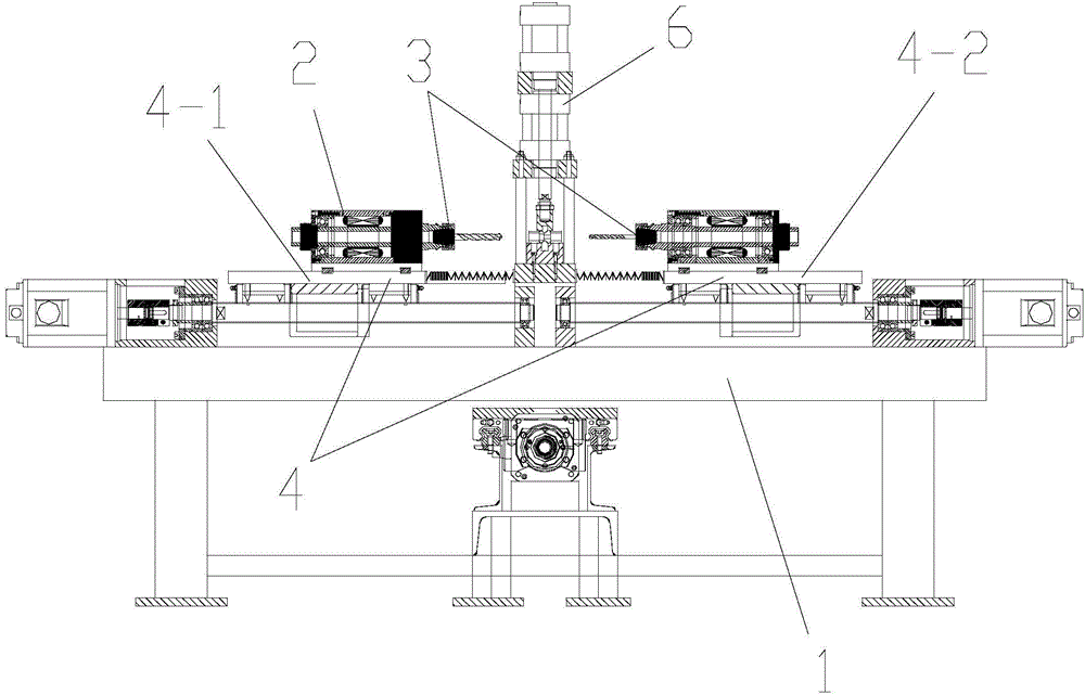
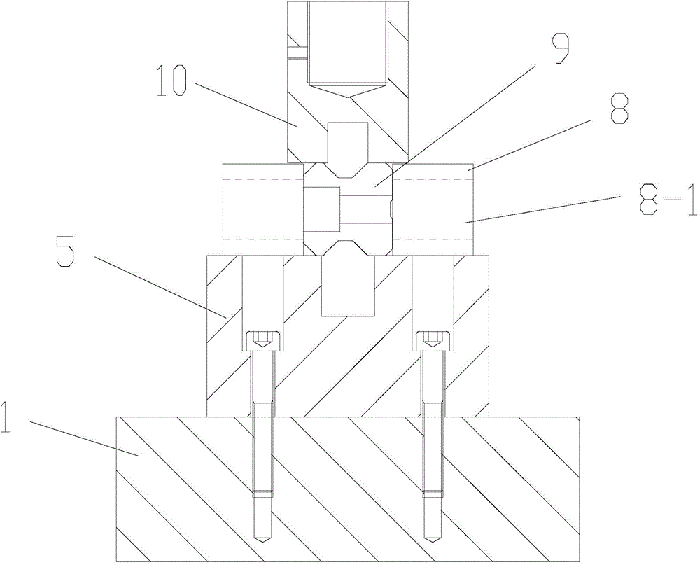
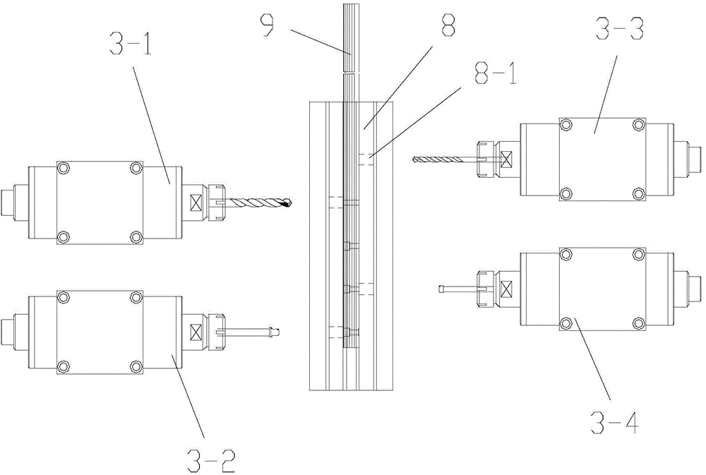
[0038] Referring to the accompanying drawings: the guide rail processing device in this embodiment includes a workbench 1, which is provided with a drilling tool spindle 3 driven by a DC synchronous motor 2, and the drilling tool spindle 3 is installed on the transverse guide rail 4 and connected to the motor drive The screw nut mechanism of the workbench 1 is equipped with a support table 5 supporting the workpiece and a compression cylinder 6 for fixing the workpiece 9. The front end of the workbench 1 is provided with a pull rod 7 for pulling the workpiece 9; the drilling tool spindle 3 includes spaced installation The left reaming machine 3-1 and the left chamfering machine 3-2 on the left side of the workbench 1, the right drilling machine 3-3 and the right chamfering machine 3-4 installed on the right side of the workbench 1 at intervals, the right drill The hole mach...


PUM


Abstract

A guide rail machining device comprises a working table. A drilling tool main shaft driven by a DC synchronous motor is arranged on the working table, arranged on a transverse guide rail and connected with a lead screw and nut mechanism driven by a motor. A supporting table for supporting a workpiece and a pressing cylinder for fixing the workpiece are installed on the working table. A pull rod for pulling the workpiece is arranged at the front end of the working table. By means of the structure, the guide rail is moved through the pull rod and fixed through the pressing cylinder, the drilling tool main shaft is only moved transversely without being moved longitudinally, and therefore the hopping of the drilling tool main shaft is reduced, and the machining quality of the guide rail is improved. The lead screw and nut mechanism driven by the motor mainly comprises a motor, a lead screw and a nut pair, wherein the motor drives the lead screw to rotate and drives the nut pair to move as well.

Description

technical field [0001] The invention relates to a machining device, in particular to a guide rail processing device. Background technique [0002] At present, the guide rail drilling process has low production efficiency and low precision, which makes the product quality poor. For example, there are generally two drilling methods: method 1. The worktable is moved and the workpiece is installed on the workbench. This mechanism requires the length of the workbench. It is longer than the length of the workpiece, and the length of the lathe is required to be longer, at least twice that of the workbench. Therefore, after the size of the bed and workbench is increased, the cost will increase, the processing difficulty will increase, and the accuracy of the workpiece will not be guaranteed; Method 2: Fix the workpiece and move the tool spindle for processing the hole, so that the size of the mechanism is reduced. However, because the tool spindle is moving, the structural rigidity ...

Claims


Application Information

Patent Timeline
Patent Type & Authority Applications(China)
IPC IPC(8): B23P23/00
CPCB23P23/00
Inventor 吕永昌
Owner LISHUI UNIV
Why Eureka
Try Eureka