Method for operating a drive device, in particular a hybrid drive device

a drive device and hybrid technology, applied in the direction of vehicle position/course/altitude control, process and machine control, instruments, etc., can solve the problems of permanent deviation, permanent balance, and the deviation of the ascertained torque of the drive unit from the target torque defined therefor

Inactive Publication Date: 2010-11-25
ROBERT BOSCH GMBH
View PDF10 Cites 13 Cited by
  • Summary
  • Abstract
  • Description
  • Claims
  • Application Information

AI Technical Summary

Benefits of technology

[0016]Finally, upon detection of an external influence on the torque in normal operation, the method changes to dynamic operation. For example, if auxiliary units are switched in, such as an air conditioner compressor, which has a sensitive effect on the operating behavior of the drive device, this prevents a torque demand from being implemented inadequately, or electronic stability programs (ESP) or interventions of automated shift transmissions from being implemented inadequately.

Problems solved by technology

Because of the inaccuracies of corresponding actuators and sensors, however, the ascertained torque of a drive unit may permanently deviate from the target torque defined therefor, in particular at high torques.
However, this has the result that permanent deviations are permanently balanced out by the electrical machine.
In this way, for example, a defined charging strategy for the vehicle electrical system of the vehicle may not be maintained in the time average, whereby the vehicle electrical system is no longer sufficiently supplied or is excessively supplied with electrical power.
However, this results in elevated emissions associated with an elevated fuel consumption.
A permanent balancing out of torque inaccuracies by interventions in the ignition angle is therefore fundamentally possible, but is inadvisable for the above-mentioned (efficiency) reasons.
For example, if auxiliary units are switched in, such as an air conditioner compressor, which has a sensitive effect on the operating behavior of the drive device, this prevents a torque demand from being implemented inadequately, or electronic stability programs (ESP) or interventions of automated shift transmissions from being implemented inadequately.

Method used


Image

  • Method for operating a drive device, in particular a hybrid drive device
  • Method for operating a drive device, in particular a hybrid drive device
  • Method for operating a drive device, in particular a hybrid drive device

Examples


Embodiment Construction

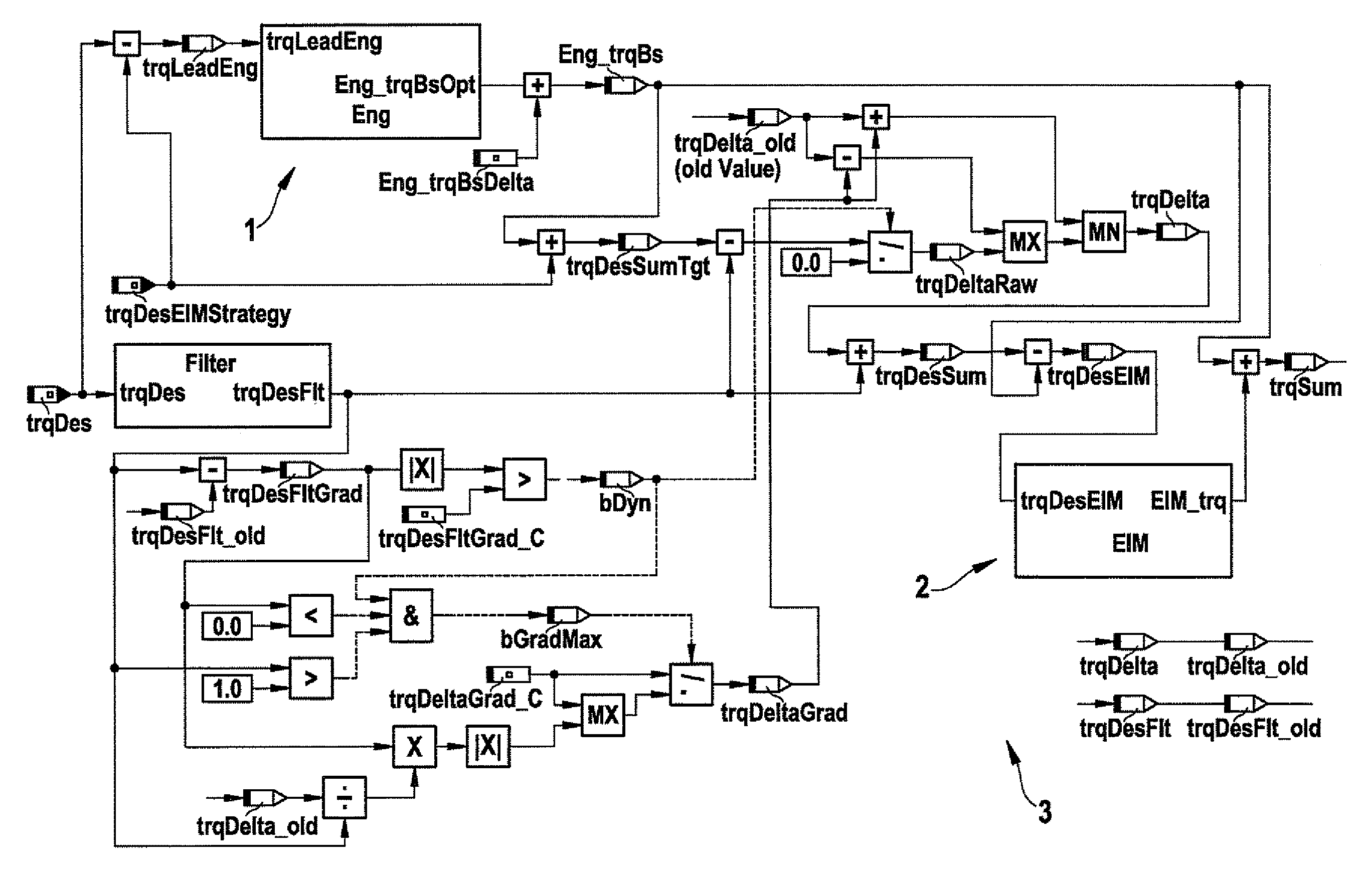
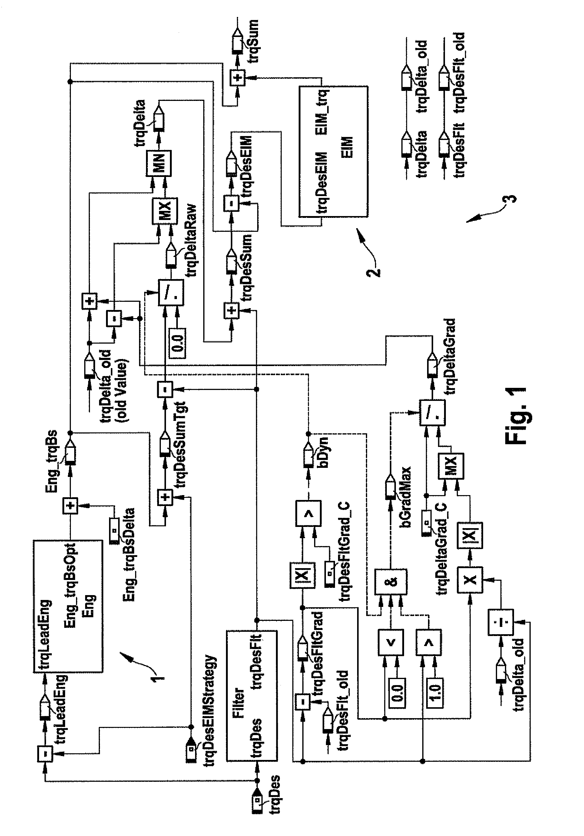
[0022]An exemplary embodiment of the method according to the present invention is shown in FIGS. 1 through 4. It is based on an internal combustion engine 1 (gasoline engine) having intake manifold injection, electronic gas pedal (E gas, electronic throttle valve), and catalytic converter. A flywheel of internal combustion engine 1 is coupled to electrical machine 2 (crankshaft starter generator). Internal combustion engine 1 and electrical machine 2 together form a drive device 3 of a motor vehicle.

[0023]Modern gasoline engines typically have an electronic throttle valve for the air mass flow rate regulation, which is activated by the engine controller. Lead target torque trgLeadEng for the internal combustion engine shown in FIG. 1 acts on an air pathway. An air mass flow rate is set accordingly by suitable activation of the throttle valve. At the ideal ignition angle, internal combustion engine 1 generates torque Eng_trqBs, which is designated as the base torque. In non-steady-st...


PUM


Abstract

A method for operating a drive device, in particular a hybrid drive device, of a vehicle, in particular a motor vehicle, having at least one internal combustion engine and at least one electrical machine as drive units, which are mechanically coupled to one another, as a function of a torque demand, in particular a filtered torque demand, in a normal operation, an ideal target torque for the particular drive unit being defined for each of the drive units and, in a dynamic operation, a target torque being defined for each of the drive units which together meet the torque demand.

Description

FIELD OF THE INVENTION[0001]The present invention relates to a method for operating a drive device, in particular a hybrid drive device, of a vehicle, in particular a motor vehicle, having at least one internal combustion engine and at least one electrical machine as drive units, which are mechanically coupled to one another.BACKGROUND INFORMATION[0002]Drive devices, which have both an internal combustion engine and also an electrical machine, are generally referred to as hybrid drive devices. The internal combustion engine and the electrical machine are mechanically coupled to one another directly or via a clutch, so that their torques add up to form a (total) drive torque of the drive device. Drive devices of this type are described, for example, in German Patent Application Nos. DE 10 2004 044 507 A1 and DE 10 2005 018 437 A1.[0003]When defining target torques for the drive units, torques of the drive units are frequently ascertained. Because of the inaccuracies of corresponding ...

Claims


Application Information

Patent Timeline
Patent Type & Authority Applications(United States)
IPC IPC(8): G06F19/00B60W30/18
CPCB60K6/485Y02T10/642B60L2240/486B60W10/06B60W10/08B60W30/188B60W2510/1005B60W2510/244B60W2540/10B60W2540/106B60W2710/0666B60W2710/083Y02T10/56Y02T10/6226Y02T10/6286B60L2240/423Y02T10/84Y02T10/40Y02T10/62Y02T10/64B60W2050/0052
Inventor FALKENSTEIN, JENS-WERNER
Owner ROBERT BOSCH GMBH
Why Eureka
Try Eureka