Automatic welding device for machining

An automatic welding and mechanical processing technology, applied in welding equipment, auxiliary welding equipment, metal processing equipment, etc., can solve the problems of affecting the quality of the weld seam, welding seam pulling and extrusion, large errors, etc., to avoid pulling or extrusion, The effect of improving welding quality

Active Publication Date: 2018-11-30
HUILIAN XINXIANG ELECTRONICS TECH CO LTD
View PDF10 Cites 13 Cited by
  • Summary
  • Abstract
  • Description
  • Claims
  • Application Information

AI Technical Summary

Problems solved by technology

[0003] Most of the existing circular seam welding is to clamp the two steel pipes through the chuck, which adopts rigid positioning, and then drives the steel pipe to rotate through the rotation of the chuck, and the welding machine welds the circular seam at the same time, although the steel pipe is welded before the circular seam welding The positioning has been carried out by spot welding, but this welding method is easy to cause the pulling and extrusion of the weld seam; because there will be a certain amount of cylindricity error in the manufacture of the steel pipe (the longer the length of the steel pipe, the greater the error), at the same time during the point During welding positioning, spot welding will also produce errors. In the end, all errors will be concentrated on the two steel pipes that are spot welded together, which will cause the cylindricity error of the two combined steel pipes to expand. When they are spot welded into a whole When the two ends of the steel pipe are clamped by the chuck, the steel pipe will not rotate in a standard circle due to the error of cylindricity, and the axis of chuck rotation will deviate from the axis of rotation of the steel pipe ring seam position. When the chuck clamps the steel pipe When the chuck rotates, it will pull or squeeze the steel pipe, which will affect the quality of the weld

Method used


Image

  • Automatic welding device for machining
  • Automatic welding device for machining
  • Automatic welding device for machining

Examples


Embodiment Construction

[0020] The following will clearly and completely describe the technical solutions in the embodiments of the present invention with reference to the accompanying drawings in the embodiments of the present invention. Obviously, the described embodiments are only some, not all, embodiments of the present invention. Based on the embodiments of the present invention, all other embodiments obtained by persons of ordinary skill in the art without making creative efforts belong to the protection scope of the present invention.

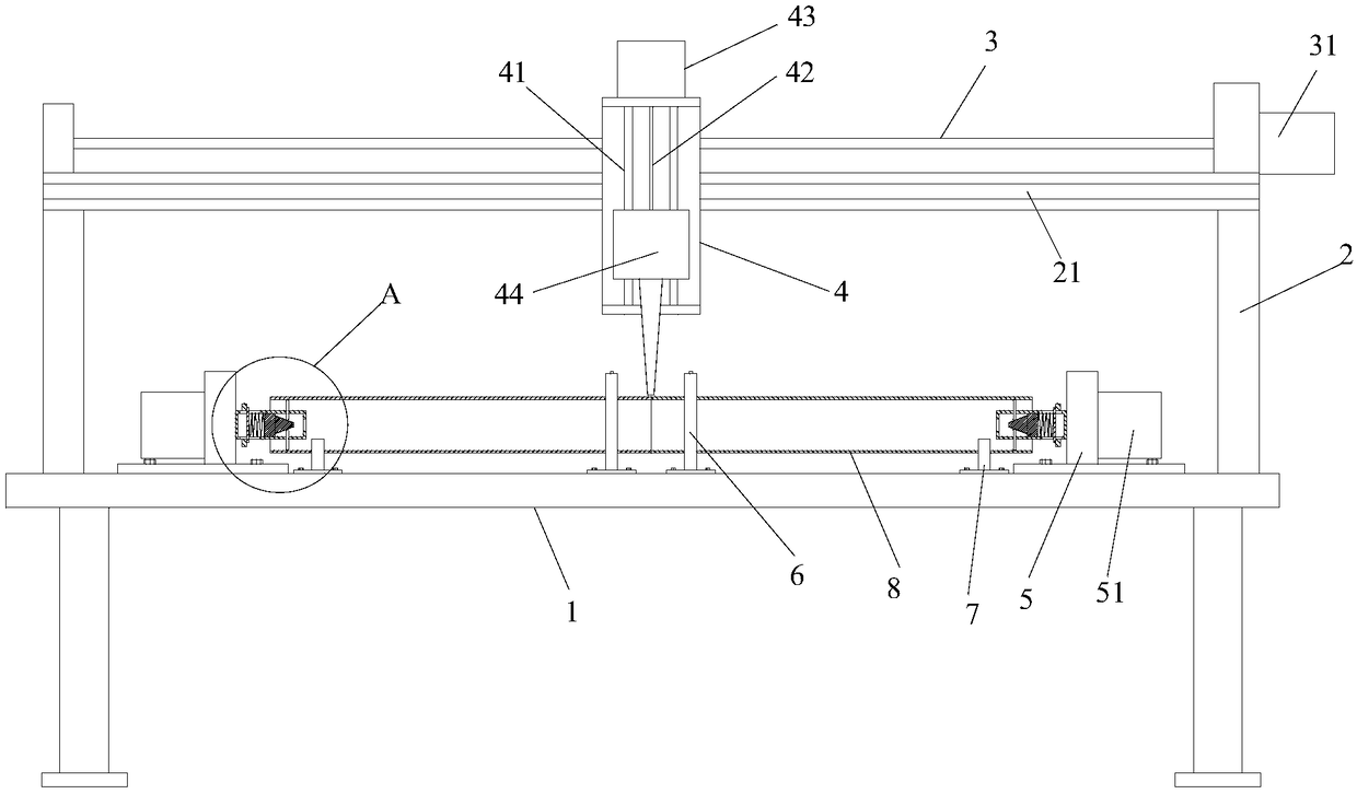
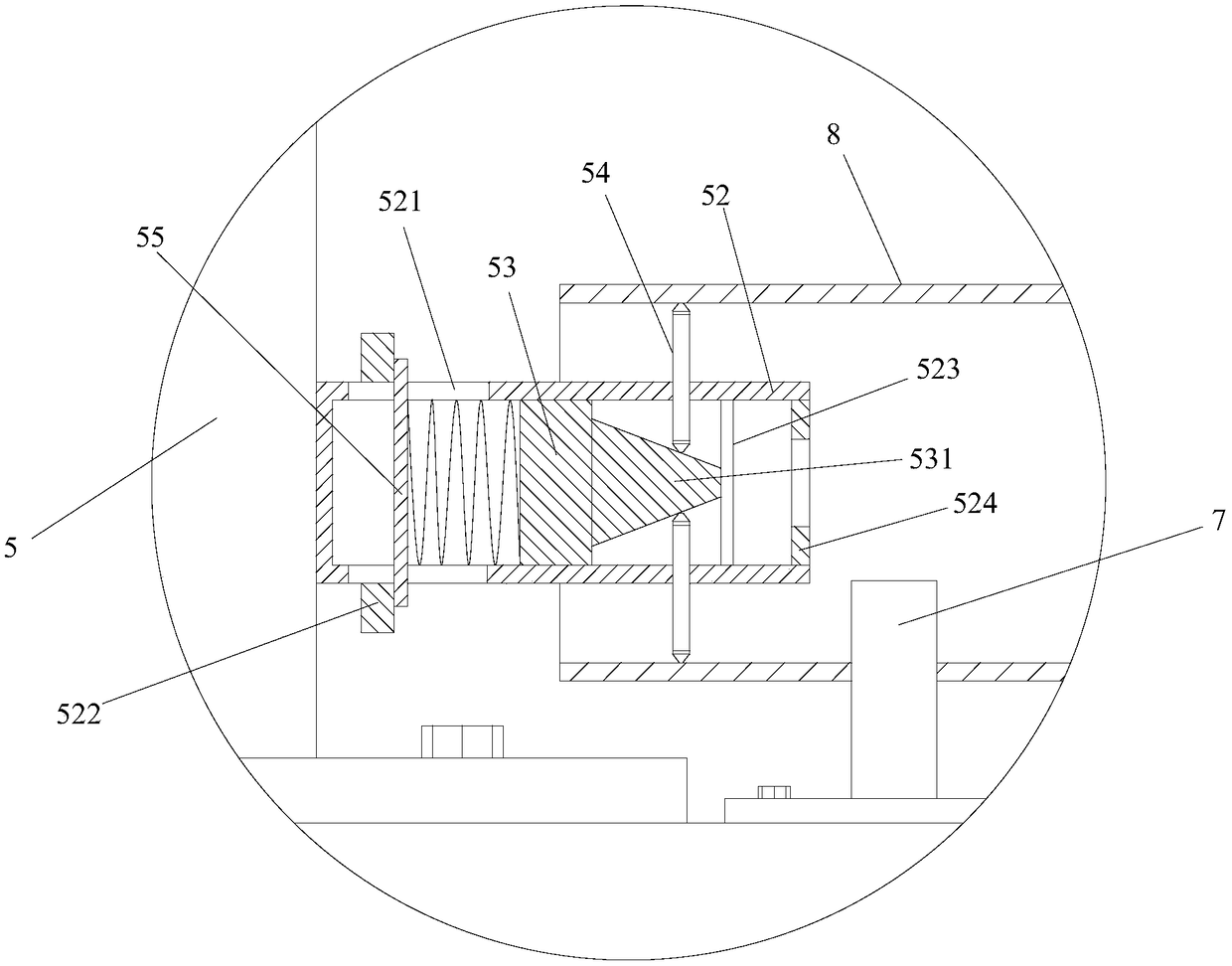
[0021] Such as Figure 1 to Figure 5 As shown, a kind of automatic welding equipment for mechanical processing includes a workbench 1, a crossbeam 2 fixedly arranged on the workbench 1, and a movable column 4 which can be arranged on the crossbeam 2, and the workbench 1 Two steel pipes 8 to be welded are installed on it, wherein the workbench 1 is a workbench used by ordinary machine tools in the prior art, and a T-shaped installation groove is opened on it, a...


PUM


Abstract

The invention discloses an automatic welding device for machining. The automatic welding device for machining comprises a workbench, a cross beam and a moving column. The moving column is provided with a welding head capable of moving. The two sides of the welding head are each provided with a first limiting unit, a second limiting unit and an adjusting seat. Each first limiting unit is close to the welding head, and each second limiting unit is close to the adjusting seat. According to the automatic welding device for machining, the first limiting units are utilized to approach to the position of a weld seam to conduct locating, so that bounce of a steel tube circular seam caused by the cylindricity error due to the self-lengths of steel tubes is lowered and transferred to the ends far away from the circular seam of the steel tubes; and meanwhile, through ejector rods on the adjusting seats, flexible transition between bounce of the steel tubes and the axis of rotating shafts is achieved when circular seam welding is conducted, since the connection strength brought by spot welding locating can be stronger than flexible fixation exerted by the ejector rods on the steel tubes, the end, far away from the circular seam, of each steel tube can bounce, and then the weld seam is prevented from being pulled or squeezed.

Description

technical field [0001] The invention relates to the technical field of welding devices, in particular to an automatic welding equipment for machining. Background technique [0002] In girth welding, the quality of the weld determines the welding quality of the two steel pipes. During girth welding, the ends of the pipes need to be ground and positioned for spot welding. The accuracy of spot welding positioning affects the later girth seam welding; [0003] Most of the existing circular seam welding is to clamp the two steel pipes through the chuck, which adopts rigid positioning, and then drives the steel pipe to rotate through the rotation of the chuck, and the welding machine welds the circular seam at the same time, although the steel pipe is welded before the circular seam welding The positioning has been carried out by spot welding, but this welding method is easy to cause the pulling and extrusion of the weld seam; because there will be a certain amount of cylindricit...

Claims


Application Information

Patent Timeline
Patent Type & Authority Applications(China)
IPC IPC(8): B23K37/053
CPCB23K37/0531
Inventor 马天凤李泽任爱梅冯振郭朝博
Owner HUILIAN XINXIANG ELECTRONICS TECH CO LTD
Why Eureka
Try Eureka