Portable electric hair dryer and mount therefor

Inactive Publication Date: 2005-06-21
HAMILTON BEACH BRANDS
View PDF30 Cites 22 Cited by
  • Summary
  • Abstract
  • Description
  • Claims
  • Application Information

AI Technical Summary

Benefits of technology

[0008]To deter theft, provision is made for storing and retaining intermediate lengths of the hair dryer's power cord around a reel located behind the wall mount and for preventing one from pulling the power cord

Problems solved by technology

The known prior art hair dryers have wall mounts with relatively complex means for supporting the hair dryers or relatively complex means for turning th

Method used


Image

  • Portable electric hair dryer and mount therefor
  • Portable electric hair dryer and mount therefor
  • Portable electric hair dryer and mount therefor

Examples


Embodiment Construction

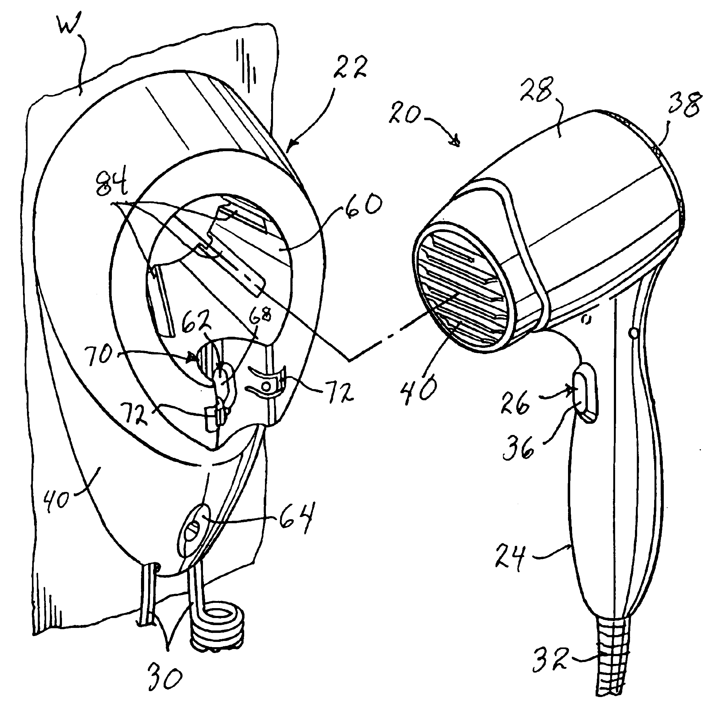
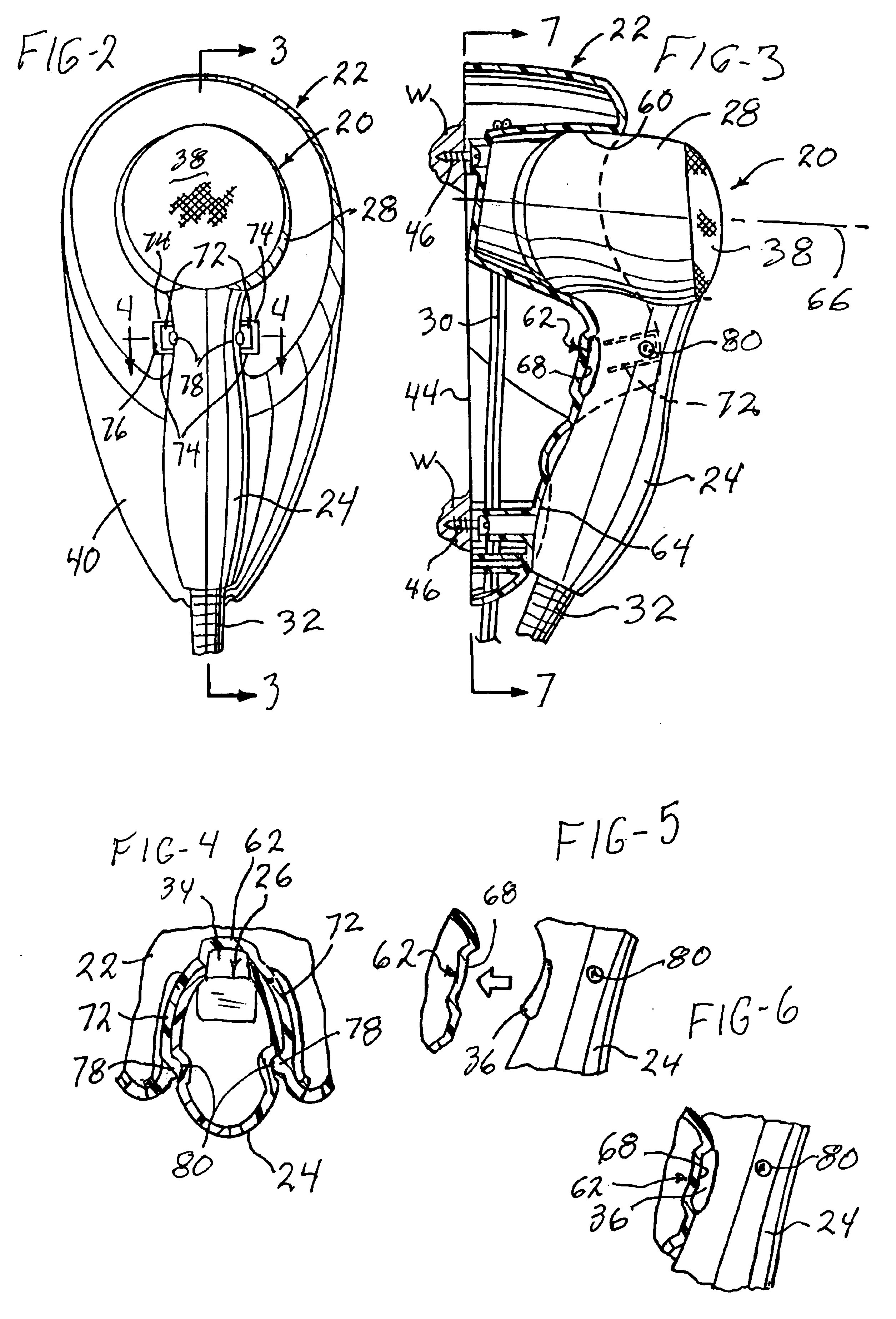
[0020]With reference to FIGS. 1 through 4, this invention provides an assembly of a portable electric hair dryer, generally designated 20, and a wall mount therefor, generally designated 22, shown mounted on a vertical wall W. The hair dryer 20 has an elongate, hollow handle 24 and a power switch 26 (FIG. 4) mounted on the handle 24 for controlling the operation of a blower motor (not shown) mounted within a tubular blower housing 28 located on top of the handle 24. A power cord 30 for connection of the hair dryer 20 to a source of house current extends upwardly through the handle 24 and out through the bottom of the handle 24 and downwardly through a cord guard 32 that depends from the handle 24. Here it may be noted that FIG. 4 is simplified because FIG. 4 shows the switch 26 without showing how the switch 26 is mounted and FIG. 4 does not show the power cord 30 or other details of construction, all of which may be entirely conventional. As shown in FIGS. 7 and 11, the free end of...


PUM


Abstract

A portable electric hair dryer has a power switch which is automatically switched off as the hair dryer is mounted on a wall mount. The wall mount comprises a one-piece molded plastic body having integrally-molded clamping jaws for gripping the hair dryer handle. To deter theft, provision is made for storing and retaining intermediate lengths for the hair dryer's power cord behind the wall mount.

Description

FIELD OF THE INVENTION[0001]This invention is directed to a portable electric hair dryer and a mount therefor. However, aspects of this invention may be used for other appliances and mounts therefor. The invention is primarily intended for use in mounting a portable hair dryer on a vertical wall but it is recognized that wall mounts can also be used for mounting hair dryers on horizontal or sloping surfaces, and this invention may similarly be used.BACKGROUND OF THE INVENTION[0002]Various wall mounted, portable hair dryers have been proposed and marketed. These often are provided with an arrangement for ensuring that the hair dryer is switched off when the hair dryer is placed on the wall mount. The known prior art hair dryers have wall mounts with relatively complex means for supporting the hair dryers or relatively complex means for turning the hair dryers off when placed on their wall mounts.[0003]The hair dryer and wall mount of this invention are designed for commercial use suc...

Claims


Application Information

Patent Timeline
IPC IPC(8): A45D20/00A45D20/12A47J45/00A47J45/02
CPCA45D20/12A47J45/02A45D2020/128
Inventor CRUZ, ANTHONY V.
Owner HAMILTON BEACH BRANDS
Why Eureka
Try Eureka