Method for producing a cover that can be placed on the end of a motor vehicle exhaust pipe, and a cover produced according to this method

a technology of motor vehicles and exhaust pipes, which is applied in the direction of mechanical equipment, domestic applications, applications, etc., can solve the problems of high labor costs and high cost of producing covers in this way, and achieve the effect of less valuabl

Inactive Publication Date: 2008-12-16
NEEF
View PDF18 Cites 7 Cited by
  • Summary
  • Abstract
  • Description
  • Claims
  • Application Information

AI Technical Summary

Benefits of technology

[0006]It is one object of this invention to provide a method of the type mentioned above but in which covers can be produced in one piece without welding work and without the finished cover experiencing impairments which make the cover less valuable or even turn it into waste.
[0008]It is important that these method steps are performed directly, such as in short periods of time, one after the other. Because the axial dimension of the cover is considerable for a deep-drawing method, the deep-drawing process occurs in several deep-drawing steps with diameters decreased in steps and a shell length increased in steps. These are followed by the method steps for forming the two open front faces of the cover, wherein the crimped rim and the tapered end section of the cut-off shell result in the final shape of the cover by appropriate method steps.
[0011]So that the front face of the cover facing the motor vehicle, and possible openings and / or holes in the shell of the beaker can be cut in a simple manner, in one embodiment the cutting-off of the shell to the required length and the cutting of the condensate drain opening and / or fastening hole are performed together. These method steps can be performed together because they are performed in the same processing direction.
[0013]A cover produced in accordance with this invention is distinguished because it is embodied in one piece in a sleeve-like manner, wherein a front end, which is inclined with respect to the longitudinal axis, has an end crimped in the shape of an arc of a circle, and the other front end extending perpendicularly with respect to the longitudinal axis in the adjoining end section has a diameter which is less than the diameter of the remaining shell. The crimped end provides stiffening and avoids sharp edges, while the tapered end section stabilizes the drawn cover and prevents undesired contractions of the material because of tensions occurring in the material.

Problems solved by technology

This requires a considerable outlay for labor, particularly during the manufacture and finishing work for the weld seam.
Thus, covers produced in this way are very expensive.

Method used


Image

  • Method for producing a cover that can be placed on the end of a motor vehicle exhaust pipe, and a cover produced according to this method
  • Method for producing a cover that can be placed on the end of a motor vehicle exhaust pipe, and a cover produced according to this method
  • Method for producing a cover that can be placed on the end of a motor vehicle exhaust pipe, and a cover produced according to this method

Examples


Embodiment Construction

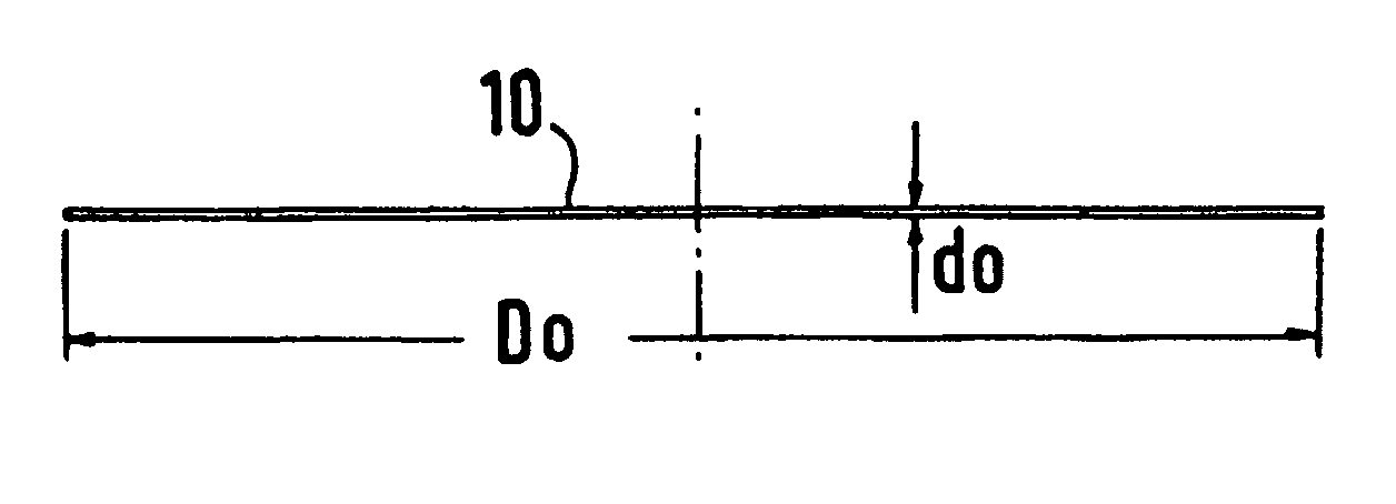
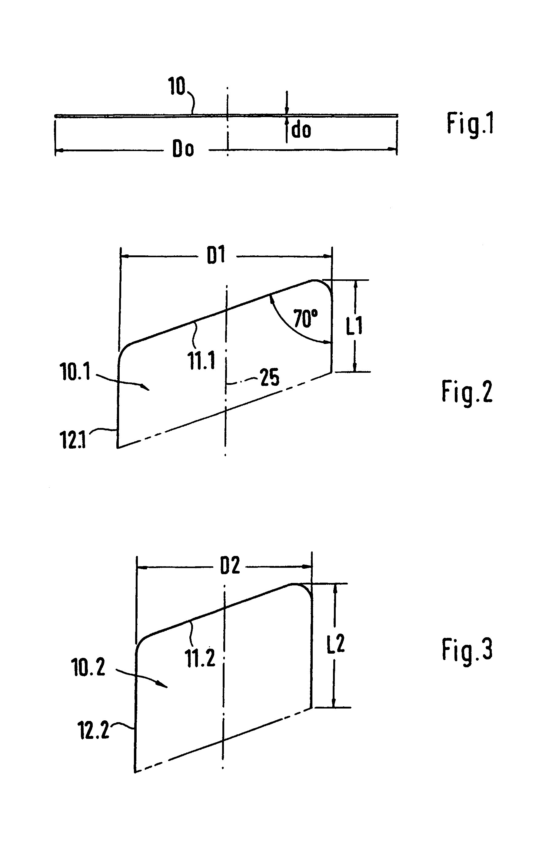
[0027]The circular blank 10 represented in a lateral view in FIG. 1 is produced, preferably cut, from a special steel plate which can be deep-drawn, of a diameter D1 of 190 mm, for example, and a thickness of 1 to 1.2 mm, for example.

[0028]In a first deep-drawing process, a beaker 10.1 with an inclined bottom 11.1 is drawn by a deep-drawing process, with a diameter D1=117.7 mm, and the shell 12.1 is brought to a shell length L1. In this case the inclination of the bottom 11.1 with respect to the longitudinal axis 25 of the beaker 10.1 on a diameter is 70° or 110°, as shown in FIG. 2.

[0029]In the following second deep-drawing process, the beaker 10.2 is drawn with a smaller diameter D2=96.95 mm, but a greater length L2 of the shell 12.1, so that the beaker 10.1 in accordance with FIG. 1 becomes the beaker 10.2, as shown in FIG. 3.

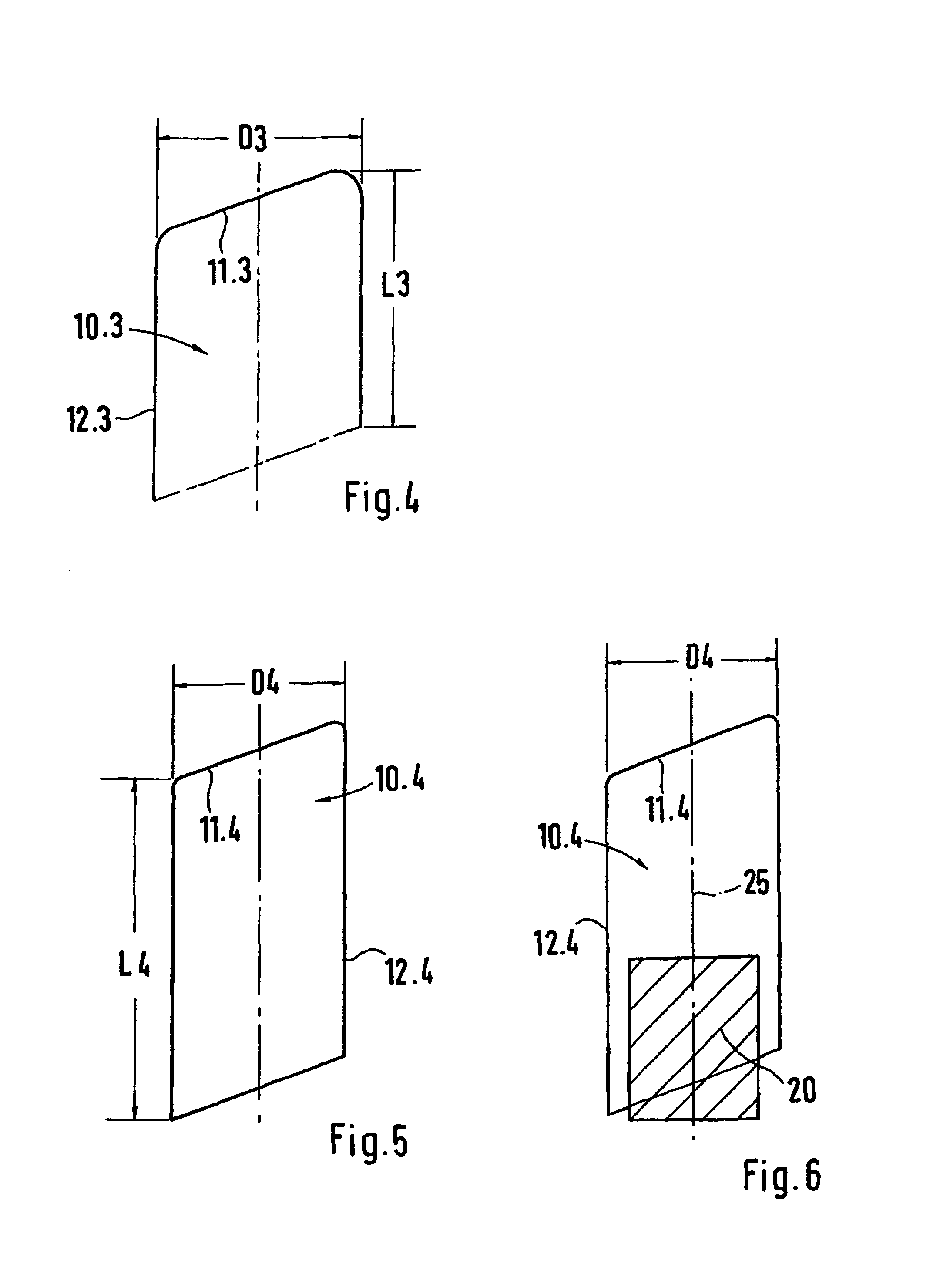
[0030]A further, third deep-drawing process follows, in which the beaker 10.2 in accordance with FIG. 3 is changed into a beaker 10.3 in accordance with FIG...


PUM

PropertyMeasurementUnit
thicknessaaaaaaaaaa
diameter D1aaaaaaaaaa
thicknessesaaaaaaaaaa

Abstract

A method for producing a cover, wherein a special steel blank is deep-drawn and can be placed on an end of a motor vehicle exhaust pipe. Immediately successive method steps makes it possible to economically produce a one-piece cover without subjecting the surface to deterioration and subsequently working the same.

Description

BACKGROUND OF THE INVENTION[0001]1. Field of the Invention[0002]This invention relates to a method for producing a cover made of a special steel blank which can be deep-drawn and placed on the end of a motor vehicle exhaust pipe, and a cover produced in accordance with this invention.[0003]2. Discussion of Related Art[0004]Known covers are used as an ornamentation on an end of an exhaust pipe protruding from the rear of a motor vehicle. For this reason the non-rusting basic material, the special steel, and the appearance of the surface of the cover are of decisive importance.[0005]Similar known covers are bent from a special steel blank into a sleeve-shaped body and are welded together at the joint on the shell circumference. This requires a considerable outlay for labor, particularly during the manufacture and finishing work for the weld seam. Thus, covers produced in this way are very expensive.SUMMARY OF THE INVENTION[0006]It is one object of this invention to provide a method of...

Claims


Application Information

Patent Timeline
Patent Type & Authority Patents(United States)
IPC IPC(8): B21D51/16F01N13/20B21D53/88B23P15/00F01N13/08F01N13/12F01N13/18
CPCB21D53/88B23P15/00F01N13/082F01N13/1872F01N13/18B23P2700/03Y10T29/49996Y10T29/49398Y10T29/49995
Inventor NEEF, MANFRED
Owner NEEF
Why Eureka
Try Eureka