Crystal oscillator circuit

A crystal oscillator and oscillator technology, applied in electrical components, generator start-up, automatic power control and other directions, can solve the problems of weak driving ability, limited application scenarios, low technical difficulty, etc. Gain control, wide application scenarios, strong driving ability

Pending Publication Date: 2022-04-12
苏州领慧立芯科技有限公司
View PDF0 Cites 0 Cited by
  • Summary
  • Abstract
  • Description
  • Claims
  • Application Information

AI Technical Summary

Problems solved by technology

In order to reduce the power consumption of the crystal oscillator circuit, the common method is to reduce the bias current of the oscillator circuit, but the method has the advantages of low technical difficulty and low cost, but the driving ability provided by the circuit itself is not strong, and the application scenarios are limited.

Method used


Image

  • Crystal oscillator circuit
  • Crystal oscillator circuit
  • Crystal oscillator circuit

Examples


Embodiment

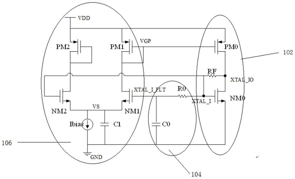
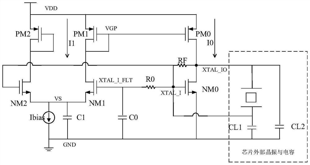
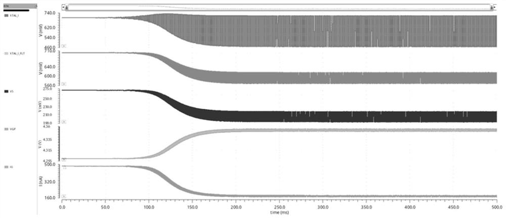
[0044] figure 1 A schematic circuit diagram of a crystal oscillator circuit according to the present invention is shown. figure 2 A complete circuit structure diagram of a crystal oscillator circuit and an external crystal oscillator according to the present invention is shown. image 3 It shows the internal signal waveform when the crystal oscillator of a crystal oscillator circuit according to the present invention is working.

[0045] to combine figure 1 , figure 2 and image 3 As shown, the crystal oscillator circuit includes: an oscillator drive module 102, a first-order filter module 104, and an amplitude detection and current bias adjustment module 106; The connection terminal is connected to drive the crystal oscillator; the first-order filter module 104 is connected to the oscillator drive module 106, and is used to filter out the AC signal at the first connection terminal of the crystal oscillator; the amplitude detection and current bias adjustment module 106 ...


PUM


Abstract

The invention discloses a crystal oscillator circuit. The crystal oscillator circuit comprises an oscillator driving module, a first-order filtering module and an amplitude detection and current bias adjustment module, the oscillator driving module is respectively connected with the first-order filtering module and the amplitude detection and current bias adjustment module, and is used for driving the crystal oscillator; the first-order filtering module is respectively connected with the oscillator driving module and the amplitude detection and current bias adjustment module and is used for filtering an alternating current signal of a first connecting end of the crystal oscillator; and the amplitude detection and current bias adjustment module is respectively connected with the first-order filtering module and the oscillator driving module, and is used for detecting the oscillation amplitude of the crystal oscillator and dynamically adjusting the bias current of the oscillator driving module. According to the invention, the bias current of the driver at the initial moment is relatively large, so that enough driving capability is ensured. As the oscillation signal gradually rises, the bias current gradually drops, automatic gain control is realized, the power consumption of the circuit also gradually drops, and meanwhile, the crystal oscillator circuit is high in driving capability and wide in application scene.

Description

technical field [0001] The invention belongs to the technical field of electronic circuits, and more specifically relates to a crystal oscillator circuit. Background technique [0002] Crystal oscillators are widely used in modern wireless communication chip systems, and low-power crystal oscillator circuits have become one of the essential components in application scenarios such as the Internet of Things and wearable devices. In order to reduce the power consumption of the crystal oscillator circuit, the common method is to reduce the bias current of the oscillator circuit, but the method has the advantages of low technical difficulty and low cost, but the driving ability provided by the circuit itself is not strong, and the application scenarios are limited. . [0003] Therefore, a crystal oscillator circuit with strong driving capability, wide application scenarios and low power consumption is especially needed. Contents of the invention [0004] The purpose of the p...

Claims


Application Information

Patent Timeline
Patent Type & Authority Applications(China)
IPC IPC(8): H03L3/00H03L5/00
Inventor 李雪民
Owner 苏州领慧立芯科技有限公司
Why Eureka
Try Eureka